How to wire coils & drivers to I/O boards in a FAST Nano-controlled pinball machine
Wiring, high voltage, and electricity can be dangerous. Read this first!
The voltages and electricity discussed here can be dangerous and could cause property loss or death. It is your responsibility to ensure you are aware of these risks and comfortable with these processes. Furthermore your local jurisdiction may have regulations or rules which differ from what we discuss here, including wiring colors, standards, techniques, etc. Although based on broadly adopted methods, FAST Pinball does not employ Professional Engineers and this information is not professional recommendations. There may be errors, omissions, or typos here. Any pinball machine available to the general public should be reviewed by a licensed Professional Engineer in your region. Use this content at your own risk.
This guide is old (for FAST Nano-powered machines only)
This wiring guide is for pinball machines powered by a FAST Nano Controller. If you have a FAST Neuron Controller, please see the Neuron wiring guide.
This guide explains how to wire drivers when you're using the FAST Pinball Modern Platform. Drivers are typically solenoids (also called "coils"), but could also be magnets or motors or other high-current on/off type devices. In this guide, we'll refer to all of them as "coils", but the general principles covered here apply to all types of driver wiring.
In FAST-powered modern machines, we suggest (and all of our documentation is written for) using 48V DC for your high voltage drivers. Machines from decades ago used different voltages, including 70V DC for original WPC-era machines, but the industry has moved to 48V DC as it is technically considered "low power" and is not as strict with the wiring regulations. And it's safer in general.
Note that in the days before LEDs, flashers were controlled as drivers, and sometimes general illumination (GI) strands were too. In most modern machines, those are replaced by LEDs which are controlled like regular LEDs. (Though there are some super bright LEDs that are still controlled like drivers, or other special purpose LEDs like single-color, non-serial ones which might be built into a start button.)
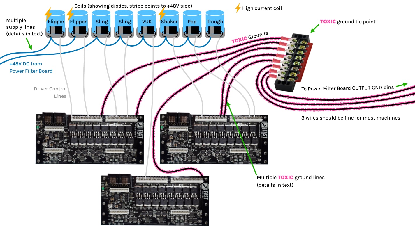
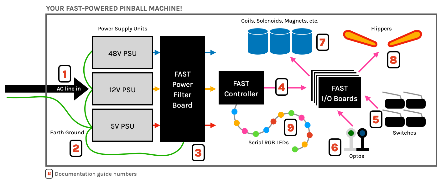
This diagram shows everything related to drivers and I/O boards. You can click on it to zoom in and we'll step through it below.
Wire type
Drivers require more current than switches, so you need thicker wires. Refer to our guide on pinball wiring standards for more specifics. For our diagrams, we use blue for the +48V supply line from the power supply to the solenoid, gray or white for the solenoid control line back to the I/O board driver output, and black for the toxic ground from the I/O board to the ground tie point.
Do you need diodes on coils? Yes!
Before we get into the specific wiring guidance, let's discuss diodes on coils. The easy advice here is YES, put diodes on coils (and magnets). The reason for this is that when the magnetic field collapses after the coil is turned off, that action causes voltage to be injected backwards into the lines, and the diode on the coil prevents that high current from going back into the FAST I/O board and damaging it. (If you're a geek and want to know more, do an internet search for "what is a flyback diode?".)
While the FAST I/O boards include transient voltage suppressors to protect the boards in these situations, it's not possible to know every scenario. (For example, large high voltage magnets will require an appropriately-sized snubber rather than a diode.) So the best practice is to install your own diodes which are tuned for the coil or device they're connected to.
For regular coils, we suggest either 1N4001, 1N4004, or 1N4007 diodes (doesn't matter which) that only cost a few cents each. Install the diode so the side with the stripe is facing the positive (blue wire from your power filter board) wire.
By the way, you might be slightly confused because switches in the FAST Modern Platform do NOT require diodes (since they're all direct and there's no switch matrix). So if you're thinking, "I thought FAST didn't need diodes", that's NO diodes for switches but YES diodes for coils.
How a FAST I/O board fires a coil
Wiring your coils will make more sense if you have a solid understand of how a FAST I/O board actually fires a coil. So to do that, let's imagine the simplest coil circuit possible.
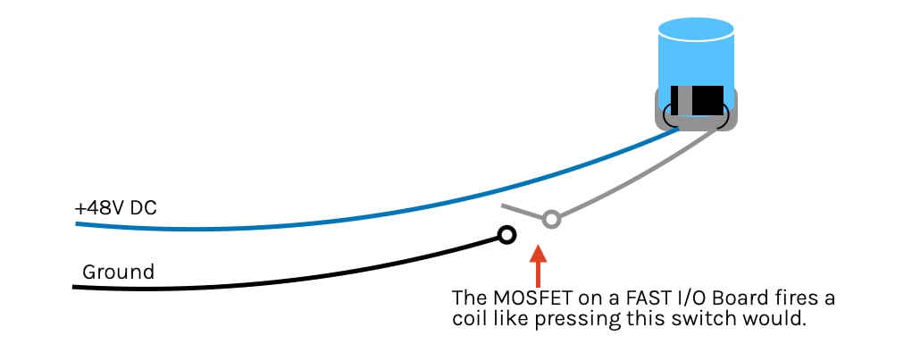
In the drawing above, +48V DC is always on and goes to the coil (blue wire). The coil is juiced at all times and just ready to fire—it just needs a connection to ground. That ground connection coming off the coil (gray wire) is going to one leg of a simple switch, and then the other leg of that switch (black wire) goes back to the ground (negative) side of that +48V DC. The simplest circuit possible. Push the switch, coil activates!
This is exactly what the FAST I/O board is doing to fire a coil. The only difference is that instead of a mechanical switch, it's an electrical switch (in the form of a MOSFET transistor). But you could imagine it like this:
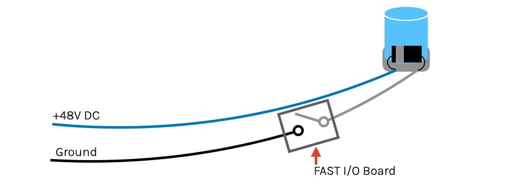
So this explains how the wiring works, why your +48V DC does not go to the I/O board, why only one "leg" of the coil goes to the I/O board, and why you need to connect the ground (or "toxic ground", since it fluctuates so much due to the high current and resistance) from the I/O board back to your toxic ground tie point.
+48V DC power wiring to coils (blue wire)
Based on the drawings above, you can see that the +48V DC power wiring is pretty straightforward. Just run the blue +48V wire from either your power filter board, or from your +48V distribution terminal. (Recall this +48V will be supported by those large capacitors on the power filter board which will dump their stored energy into the line when the voltage drops due to the high current demands of the coil coupled with the inevitable resistance in the wires.) Just solder the blue +48V supply line wire to the same coil lug which has the diode stripe. (Or add the diode now if you don't have it.) Note that single-wound coils do not have polarity since they're just a long coiled wire. The diode is what adds the polarity. (Dual-wound flipper coils are slightly more complex and will be covered in the next guide which is dedicated to flipper wiring.)
Obviously you have lots of coils in your machine, and since the blue wire is just supplying uncontrolled +48V, you can simply daisy chain blue wire connections from coil to coil. You'll need to actually solder the wire to the coil (as opposed to a crimp-on connector), though if you'd like to make your coils easy to move or disconnect, you can crimp a Molex-style connector into your coil wires a few inches from the coil. (Our skills guide to crimping covers how to do this.)
Running multiple +48V DC blue wires
Recall from our guide to grounds and grounding (which you definitely read, right?) that wire has resistance, and when a given current moves through resistance, voltage drops. (This is why the power filter board has those huge capacitors, to help make up for the drop in voltage.) But we still need to ensure the pathway is wide enough to allow enough current to get through. The "path" in this case is the wire.
A great analogy is to think about electricity and wires like water and pipes. Voltage is like water pressure, current (amps) is like the volume of water, and power (watts) is the product of pressure and volume. And, just like electrical wire where larger diameter wire supports more current (amps), larger diameter pipes support more water volume.
A correctly designed plumbing system requires different amounts of water pressure and volume for various appliance, and the diameter of pipes is intentionally chosen to support those needs. (Ice-maker is ¼", sink is ⅜", bathtub is ½", fire hose is 4", etc.) For the whole system to work, you start with larger diameter pipes and branch out as needed, with different sizes going to different things.
Electricity requires a complete circuit to work, but so does water! The plumbing drain lines are like your electrical ground returns. If you have a ½" supply line (at 70 psi) to your tub, you wouldn't want a ¼" drain line because it would take days to drain it!
So we need to think like this when we're doing designing our wiring. For example, you will most likely have dozens of coils in your pinball machine. IF you just daisy-chained a single 18-gauge +48V blue wire to every coil in your machine, that would be like daisy chaining a single ⅜" supply pipe to every appliance in your house! Sure, if you have a tiny home with one sink and one toilet, a single supply line is fine. But if you have a larger house with a kitchen and multiple bathrooms and faucets and spigots, you need to branch out and run the proper pipes in the proper orders.
Take a look at the drawing below:
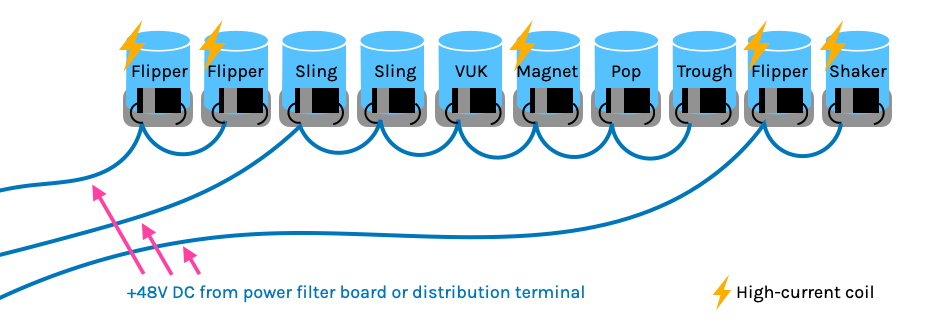
First, note that we've used the lightning bolt to identify the high-current coils. High-current coils include things like:
- Flippers (the power winding, specifically)
- Magnets
- Shaker motors (small playfield motors are not high current)
- Drop target resets (maybe? depends how many targets and how large the coil is)
- Others? Maybe?
If you want a very broad rule-of-thumb, we like to say that you should only have 2 high-current coils per +48V DC blue wire run. The lower current coils (which are everything else: trough, VUKs, pops, slings, diverters, etc.) don't matter as much in this calculation. You could have lots of coils on the same +48V DC run, like 2 high current ones plus a bunch more lower current ones.
If you want to get fancy, you could start to think about situations where various things will be on at the same time. Like if you have a mode where the player could be flipping, and you have some magnets, and you have a shaker motor, those could all be in use at the same time so maybe you'd want to ensure those are on separate runs and then wire in everything else to those same runs based on proximity and convenience.
One important thing to remember is that running additional +48V DC supply lines doesn't magically give you more current. It just helps to ensure that the wire runs are not the limiting factor in terms of transmitting power from your +48V supply (with those huge capacitors) to the devices using that power. (In other words, those nice big caps won't be too effective if you're choking them down via a single lone 18-gauge supply wire!)
All that said, there are no specific hard and fast rules here. You may have to experiment a bit, and every machine will be different. So just be aware of this concept, but don't overthink it. You may just say, "I want to be super safe so I'll run a dedicated +48V DC supply line to every high-current driver!" Our response would be, "Eh, that's fine, it's just a lot more wire which is more expensive and time-consuming and heavier and really it's not needed. (But you do you!)"
Be sure to read the next section on flipper wiring and the final section on overall machine power distribution before you actually start cutting and soldering, but with the guidance provided here you should be in great shape.
Coil return to I/O board (gray/white wire)
Next for your coil wiring is the driver control line which you solder to the other coil lug (side attached to the diode without the stripe) which runs to the numbered driver control pin on the FAST I/O board header. We typically use white wire (also 18-gauge) for this, though our diagrams use gray since it's easier to see. Gray or white in real life is fine.
Wiring this is also straightforward. Crimp on a pin and insert it into a 12-pin or 7-pin (depending on which model I/O board it's going to) 0.156" female connector. Since this is the wire that actually fires this specific driver, there is no branching or splicing or calculations involved here. Coil lug to I/O board connector. Done!
Here's a photo of the driver control header from a FAST I/O board:
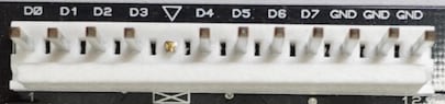
You will be connecting this white/gray wire to one of the "D" pins (D0-D7 in this photo). Be sure to put a key plug in the key pin location, especially if you have a 1616 I/O board since that board has two driver control headers and you don't want to mix them up in the future.
I/O board toxic ground (black wire)
The final connection to complete the coil wiring circuit is the black toxic ground wire which goes from the I/O board back to the ground tie point. (And possibly through a terminal barrier collection point in the middle.) This is the "toxic" ground and should not be mixed or combined with any other grounds except at your single ground tie point. (More on that in that final overall machine power distribution guide.)
Why do you keep saying "toxic" ground?
Let's pause for a moment and revisit this toxic ground subject. Recall from our guide to grounds and grounding (which you definitely read, like for real actually read, right?) that when a high-current load (like a coil) is activated, the resistance in the circuit will cause the supply voltage to drop and the ground level (which is supposed to be zero volts) to rise. This happens in all circuits (since in the real world they all have resistance), though with your 5V and 12V and other lower current things, or things that are not changing current demands so rapidly, this amount is so low it doesn't matter. But with coils, their ground return could fluctuate by one volt or more, which can be ok when you have a total of 48 volts, but would be bad if you had more than a full volt of fluctuation on a 5V or 12V circuit.
Because of this, it is CRITICAL that the ground lines for your coils and drivers are NOT connected to any other ground lines in your machine (except at that single ground tie point near your power supply). This is so important that we call these driver grounds "toxic grounds" and show the pink fuzz around them in our drawings, so that you don't think they are regular grounds that can be randomly shared between other things.
So going back to our simple coil circuit from before, this is a more accurate representation of what's happening in real life:
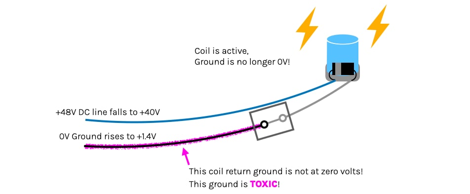
When that high load coil is activated, the instant rush of all that current over those wires with resistance will cause the +48V line to drop, and the (toxic) ground line to rise above zero, so as mentioned in the grounding guide, if you have something on your 5V or 12V bus connected to that toxic ground, then your 5V ground will rise too meaning you actually drop the available voltage to your 5V things and you'll get brownouts, processor resets, etc. (And when the high current driver is turned off the whole thing could happen in reverse and you might get too much voltage on your 5V bus since the ground would be less than zero volts.)
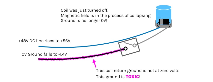
And remember this ± 1.4V (or more) swing on the toxic ground is happening all the time, when any coil is fired or released (not just from the high current ones). Multiply that by all your drivers in your machine, and you get it. So keep everything else away from that toxic ground and you'll be fine.
How many toxic ground wires from each I/O board?
The final coil wiring aspect to consider is how many toxic grounds you'll run from each I/O board. For sure, you must have at least one or your coil won't work. :) But notice in the driver header photo above that the 12-pin header which connects up to 8 drivers has three "GND" pins. What??
The reason for this is that you can connect multiple parallel toxic grounds which is important when you have multiple coils firing at the same time from the same board. (Going back to our water analogy, this would be like connecting additional drain pipes to a plumbing fixture we don't want to get backed up when a bunch of water is dumped in it all at once.)
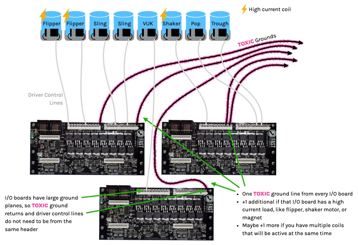
Take a look at the same drawing from the beginning of this guide but with a focus on the toxic grounds: (click to zoom in)
Again there are no hard and fast concrete rules here, but we can provide some guidance that should work for most situations:
- First, one run toxic ground line from each I/O board. The coils will not work without at least one.
- Next, add one additional toxic ground line if that I/O board has a high-current driver (see the list above).
- Finally, count up how many drivers connected to that single board could be active at the same time, and make sure you have at least that many toxic ground lines.
Again there are exceptions. At the end of the day, it's all about ohm's law and math. If you have 2 or 3 drivers which are super low current (maybe a few gates), those will be low enough that you don't need to count them as "2" for the math when you're figuring the number of toxic grounds.
All that said, more grounds are better, so if you're on the fence about things, just run another one. That doesn't mean you should automatically use every GND pin, since adding too much ground doesn't help and it just means more wire, expense, time, and weight, but again if you really want to, go for it. (People designing machines for commercial production will want to test and do the real math here, since they have a good incentive to minimize the costs, but if you're building a one-off homebrew, meh, what's another toxic ground?)
Finally, know that each FAST I/O board has a large ground plane that connects all the coil return grounds together. So if you have an I/O board with multiple driver headers, you can consider the "GND" pins from all headers on the board to be the same, and it doesn't matter which sets of pins you use. If you have 3 coils simultaneously firing from the first header, and three toxic ground lines connected to the second header, that's fine.
Where does the other end of the toxic ground go?
Now that you have your toxic ground lines connected to all your I/O boards, what do you do with them? The final diagram shows this:
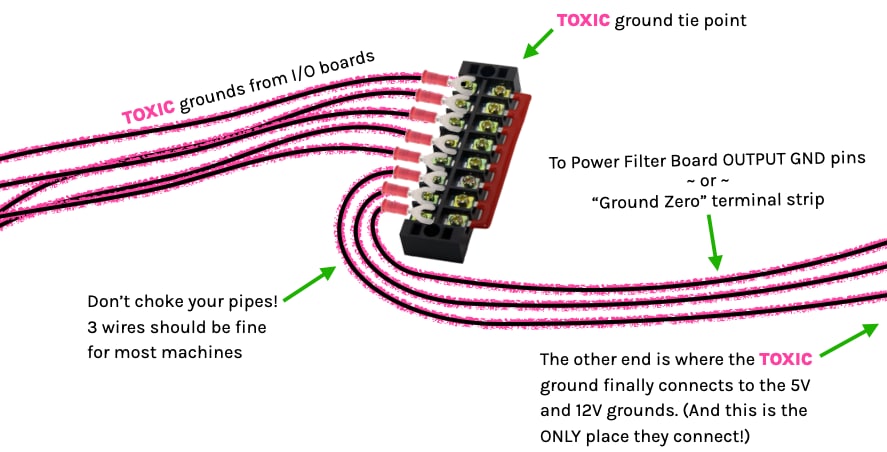
The three toxic ground wires that exit the drawing above end up at the ground tie point, which you can see in the Ground Tie Point section of our cabinet wiring diagram.
Essentially you're just connecting your toxic grounds back to the ground pins for the high voltage line output on the power filter board. However there are only two pins for this purpose, so if you have more than three toxic ground lines, you will have to connect them all together at some in-between point, reducing the wire count down to an amount you can connect into your filter board or main ground point.
To connect these wires together, just like with your AC high voltage wiring, you can either use lever wire connectors or terminal strips. Obviously you'll need enough capacity to hold all of your toxic ground lines, plus additional capacity to then continue the toxic ground onto your main tie point. For this last run, a smaller, simpler machine might be fine with two lines, though three is probably better and should be fine for most machines. Most likely you'll have some kind of terminal strip near your power supplies or filter board where you're tying all your grounds together (and possibly that's the point you tie into earth ground also), so when you're counting up connections, figure 3 for toxic ground plus whatever else you need for 5V and 12V. This is covered more in depth in the final wiring guide about putting everything together.
Why do drivers partially fire when I power the machine off?
You might notice a small "flutter" or movement of certain drivers or coils when you power off your machine. (This is most noticeable in flippers which might do a partial flip on power off.)
This is called a runt pulse and is something you can safely ignore.
If you're curious about the science behind why this happens, read on! There are a few different scenarios that cause this, all related to 12V and 48V power rails collapsing and dying at different rates when the machine is powered off.
The most common is if you power down your machine while you have autofire rules configured which include opto switches. (e.g. optos with flippers). Since the opto emitter LEDs are driven by 12V, when that voltage collapses and the emitter LED fades off, the system sees that as a switch press, and if there’s enough power left in the control circuitry and on the 48V rail then you might get a bit of an effort to pulse them as they’re dying.
Another cause which can cause the runt pulse to happen for every driver (not just autofires) again depends on how fast the 12V and 48V collapse compared to each other. The drivers on an I/O Board which control the MOSFETs are powered by the 12V, so as they lose voltage and die they could change state, and if there’s still enough 48V remaining as it’s collapsing too then you’ll end up with that little flutter. The reason it happens with some machines and not others depends on what model PSUs you have, how many filter capacitors you have, and how the voltages collapse relative to each other.
But again you can ignore this. It shouldn’t blow a fuse or be enough to eject a ball from anywhere.
This guide is part of our complete series on wiring your FAST Nano-controlled pinball machine. Click to see the rest!
Wiring guides for FAST Nano-controlled pinball machines
We have many guides and a complete wiring walk-through for your entire pinball machine powered by a FAST Nano Controller. Please read and understand all of the wiring guides before you start planning and physically wiring your machine.
Baseline wiring skills & knowledge
Important wiring and electrical background information you need to know before you start planning your machine's wiring.
FAST Nano-controlled Pinball machine wiring guides
The guides below walk you through a complete machine wiring, section-by-section. The numbers in the drawing match up to the numbers in each diagram. We assume you follow these in order. Click the image to zoom in.
N or > jump the next page, P or < for previous, search with S or ?