How to wire switches to I/O boards in a FAST Nano-controlled pinball machine
Wiring, high voltage, and electricity can be dangerous. Read this first!
The voltages and electricity discussed here can be dangerous and could cause property loss or death. It is your responsibility to ensure you are aware of these risks and comfortable with these processes. Furthermore your local jurisdiction may have regulations or rules which differ from what we discuss here, including wiring colors, standards, techniques, etc. Although based on broadly adopted methods, FAST Pinball does not employ Professional Engineers and this information is not professional recommendations. There may be errors, omissions, or typos here. Any pinball machine available to the general public should be reviewed by a licensed Professional Engineer in your region. Use this content at your own risk.
This guide is old (for FAST Nano-powered machines only)
This wiring guide is for pinball machines powered by a FAST Nano Controller. If you have a FAST Neuron Controller, please see the Neuron wiring guide.
This guide explains how to wire switches to your FAST I/O boards. (Optos are slightly more complex and covered in the next guide.) It assumes you've been following our wiring guides in order and that you have your power, FAST controller, and I/O board loop network wired up already.
All switches in your pinball machine are wired to FAST I/O boards. This includes playfield switches, stand ups, targets, optos, flipper buttons, the start button, coin switches, service buttons on the coin door--everything! Every switch in a machine built on the FAST Modern Platform is a direct switch. There are no switch matrixes anymore, and switches do not need diodes. (Coils still need diodes though, more on that in the coils wiring guide.)
By default, the FAST Pinball hardware sends an event to the host computer every time a switch changes state. (In other words, if you just tap a switch, the host computer will receive two messages: the first indicating that the switch changed from inactive to active, and a second message indicating the switch changed from active back to inactive.) You can also query the FAST system to see what state one (or all) of the switches are in at any given moment.
The FAST Pinball platform automatically handles switch debouncing. (You can configure the specifics of how this works on a switch-by-switch basis.) Switch changes are only reported to the host computer after the switch has been debounced.
Every FAST I/O board has one (or more) headers for switches. Each 11-pin (0.100") header supports eight switches. The 0804 has a single switch header, the 1616 has two to support its 16 switches, and the 3208 has four to support its 32 switches. Every switch header on every FAST I/O board has the same pinouts except for the key pin location.
Here's a close-up view of a switch header on a FAST I/O board:

This header is for switches numbered 0-7 for this I/O board. If your I/O board has more than 8 switches, you'll see additional switch headers numbered 8-15, 16-23, and/or 24-31.
Wiring up a switch is simple. Connect one leg of the switch to one of the numbered inputs, and connect the other leg to the "G" pin which is the common switch return. Simple!
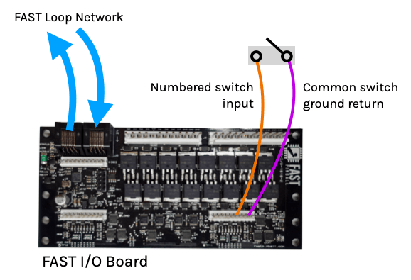
If you're following our wiring color standards, the individual switch inputs are orange and the common switch return wire is purple.
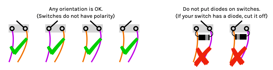
Mechanical switches do not have polarity. They can be connected either way. (Just make sure there is not a diode attached to your switch!)
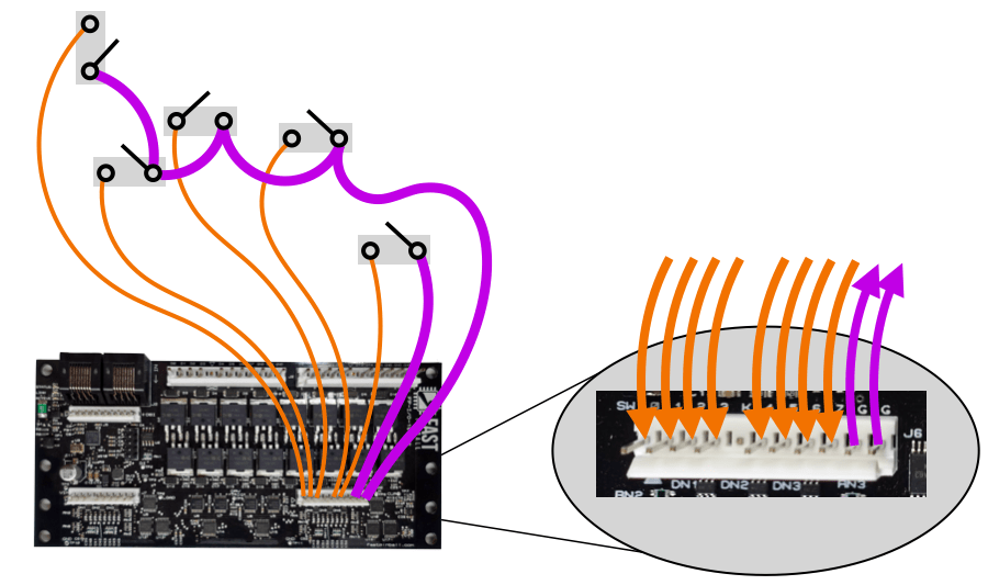
You'll notice there are only two switch ground returns on each header per eight switches. This is because you can run a common wire to one leg of all of your switches, while the other leg of each switch goes back its own numbered input pin. The reason there are two "G" switch returns per header is simply for convenience. You can just use one for all eight switches if that makes more sense based on your layout, or use both. It doesn't matter.
This is shown in the diagram below. The common purple wire is thicker just so you can see it better. The drawings make it look like a single wire is run from switch to switch, though really you'll attach two purple wires to each switch leg--one goes to the previous switch and the other to the next switch.
For I/O boards with multiple switch headers, it's ok to run the common switch return back to any switch header on the board. It doesn't have to be the same header the input wire of the switch is connected to. So this means you could have a single purple return line for more than eight switches, and it's ok if one switch's input is from one board header with its ground return going to another header. The only important thing is that you MUST run a switch's ground return back to the same I/O board that the switch is on.
The following diagram shows a few options of what's allowed and what is not when dealing with multiple I/O boards.
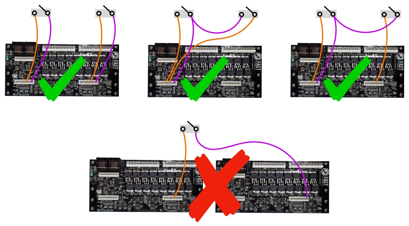
Again, both switch wires must connect to the same I/O board. We don't care which wires go to which headers--we just care that they go back to the same board.
Why is this? Refer back to the guide to grounding and how the local ground references on individual I/O boards are designed to float. The FAST I/O boards know that a switch is closed by comparing the input voltage to the ground reference voltage, and as long as they're both floating together (since they're on the same board and designed to float together), everything will be fine. But if you split the leads of a switch across two different I/O boards, you could have different ground reference points at different moments (depending on what the coils are doing at the exact second a switch is hit) and switch inputs could be missed and you could create unintended paths to floating ground across multiple boards.
So this is a mantra. Both legs of a switch must go back to the same I/O board. No exceptions.
Wire type
Switches do not require much current, so you can use thinner wires. Refer to our guide on wiring standards for more information.
That current required to run the switches is provided by the I/O board itself which receives its 12-volt supply power via the FAST I/O Loop. Standard switches do not require external power.
Normally Open (NO) versus Normally Closed (NC)
Most standard switches are a type called "normally open" which means in their normal not-active state, they are open. ("Open" means inactive, not connected, and/or circuit is not complete.) This is what a regular switch is, such as a rollover wire or a standup target.
However some switches are "inverted" in that they are "normally closed" (NC) which means they are in their closed, active state normally, and then when the ball hits them (or whatever the activation mechanism is), the switch opens. So NC switches are closed normally and then open when they are active.
From your pinball machine standpoint, it makes no difference whether a switch is normally open or normally closed. So if you have a switch situation where the switch is "closed" by default, that is totally fine. (In fact optos are like this, more in the next section.)
The specifics of how to handle a normally open versus normally closed switch are not important at this point. (If you're using MPF, it's as simple as adding type: NC to a switch config, and you never have to think about it again.)
We mention this here just for completeness. If you have a switch that's backwards, or closed/active normally and then open/inactive when a ball hits it, that's fine. You don't have to do anything different for wiring it.
Which switches connect to which boards?
We mentioned in the previous guide about FAST I/O board wiring that in a Nano-controlled machine, the order of your boards on the FAST I/O Loop affects the switch number that's reported to your host computer. From a practical standpoint, it doesn't matter which switch has which number. The software doesn't care.
That said, there are a few things to consider when you think about which switches connect to which I/O boards.
If you're using a FAST Nano Controller, then it's important that for your "quick response" switches (where a switch controls a driver and you want that driver to fire as quickly as possible when the switch changes), in these cases you want to ensure that both the driver and switch are connected to the same I/O board. This includes the switch+driver combinations for mechs like:
- Pop bumpers
- Slingshots
- Quick-action diverters with ramp/lane entry switch
- Kickbacks
- Flippers (Both flipper buttons and EOS switches)
- Etc.
The exception to this rule is the first eight switches from the first I/O board on the FAST I/O Loop. These switches can be used for "instant response" rules for any driver from any I/O board. This is typically used for the flipper buttons since they're connected to an I/O board in the cabinet while the flipper coils and EOS switches are connected to an I/O board under the playfield. In this case just make sure that your cabinet I/O board is the first one in the loop, and that the flipper buttons are connected to the 0-7 header on that I/O board. More details on this are available in the guide to wiring FAST boards.
Note that FAST Neuron-controlled systems do not have this constraint. For Neuron-controlled machines, any switch can control an "instant response" driver from any I/O board.
This guide is part of our complete series on wiring your FAST Nano-controlled pinball machine. Click to see the rest!
Wiring guides for FAST Nano-controlled pinball machines
We have many guides and a complete wiring walk-through for your entire pinball machine powered by a FAST Nano Controller. Please read and understand all of the wiring guides before you start planning and physically wiring your machine.
Baseline wiring skills & knowledge
Important wiring and electrical background information you need to know before you start planning your machine's wiring.
FAST Nano-controlled Pinball machine wiring guides
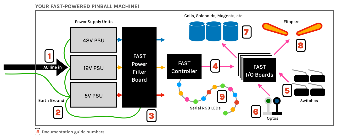
The guides below walk you through a complete machine wiring, section-by-section. The numbers in the drawing match up to the numbers in each diagram. We assume you follow these in order. Click the image to zoom in.
N or > jump the next page, P or < for previous, search with S or ?