Wiring serial RGB LEDs in a FAST Neuron-controlled pinball machine
Wiring, high voltage, and electricity can be dangerous. Read this first!
The voltages and electricity discussed here can be dangerous and could cause property loss or death. It is your responsibility to ensure you are aware of these risks and comfortable with these processes. Furthermore your local jurisdiction may have regulations or rules which differ from what we discuss here, including wiring colors, standards, techniques, etc. Although based on broadly adopted methods, FAST Pinball does not employ Professional Engineers and this information is not professional recommendations. There may be errors, omissions, or typos here. Any pinball machine available to the general public should be reviewed by a licensed Professional Engineer in your region. Use this content at your own risk.
This guide shows you how to wire up LEDs for use in your Neuron-controlled pinball machine. It assumes your expansion boards are already wired up. If not, check out that guide first.
In Neuron-controlled machines, LEDs are connected to expansion boards. (Remember that the Neuron controller has a built-in expansion board for backbox bling, so the LED ports on the Neuron are technically connected to an expansion board as well.)
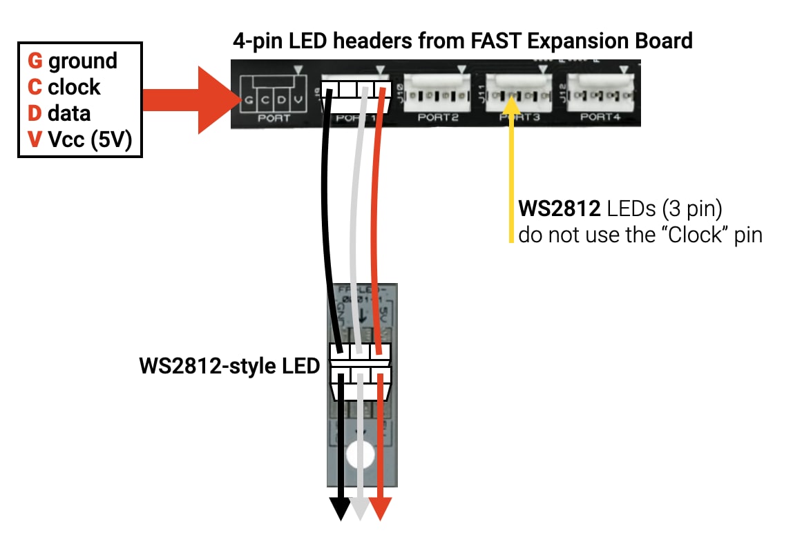
All LED ports in the FAST Modern Platform have 4 pins, meaning they can be used with WS2812-style "3-wire" LEDs, and, in an upcoming firmware update, APA102-style "4-wire LEDs." (A future firmware update will also add support for RGBW LEDs, more on that in a bit.)
In modern pinball machines, most (if not all) LEDs are RGB (meaning the software controls the color and brightness), and these LEDs are used for just about everything nowadays, including things that in the past were flashers and GI (general illumination).
The one exception in the FAST Modern Platform is for flashing cabinet buttons (typically the start button and maybe the ball launch button), and the always-on LEDs used to illuminate the coin reject mechanism in the coin door. (Those types of LEDs are controlled via the cabinet I/O board.)
Understanding Serial RGB LEDs
The first step to wiring your LEDs is to understand how they work. The types of LEDs that FAST Pinball controllers support are referred to as "serial LEDs" or "addressable LEDs". Specifically the type of LED is called "WS2812" (which is the part number of the original company who made them, though now they're available everywhere as that.)
Serial LEDs have six pins. three in and three out. The in pins are +5V, ground, and a serial data in, and the out pins are +5V out, ground, and serial data out. Each LED has a tiny microcontroller in it, plus a red, green, and blue LED element. You connect your LEDs in long chains. Each LED reads its own values from the serial line and also passes the data from the serial line down to the next LED. The LED controller (the FAST board, in this case) sends the instructions for every LED in the chain out the single serial pin.
Much much much much more has been written on the internet about serial / addressable LEDs. So rather than rehashing all that here, if you'd like to learn more, we like this guide from DeRun Lighting which is essentially "Addressable LEDs 101". If you're new to these types of LEDs, read it here.
What types of LEDs are supported?
Currently, FAST expansion boards (and the Neuron) support WS2812-compatible, 3-wire, RGB LEDs.
A future firmware update will add support for RGBW LEDs, which have a fourth element which is white. RGBW LEDs are nice (especially for GI) because the white element is more of a "full spectrum" white which allows the colors it illuminates to look more natural. RGB LEDs simulate white light by combining red, green, and blue. When the FAST RGBW LED support is added, you will be able to mix-and-match RGB and RGBW LEDs in the same chain (assuming they both use the 3-wire system).
Another future firmware update will add support for APA102-compatible LEDs. These types of LEDs use a 4-wire system. Similar to the 3-wire system, the 4-wire system has 5V, ground, and data wires, but it also adds a fourth "clock" wire, which is used to control how fast the LEDs update. APA102 LEDs can be driven faster (for less flicker) and are just starting to gain in popularity.
Once we release the firmware update for APA102-style LEDs, you will be able to mix-and-match LED types on the same board, but each port will need to be only 3-wire or 4-wire LEDs (which makes sense, since all the LEDs in a single chain will need to have the same number of wires).
APA102-style LEDs are also available in RGBW variants which will be supported in the future.
Wiring WS2812-style, 3-wire LEDs
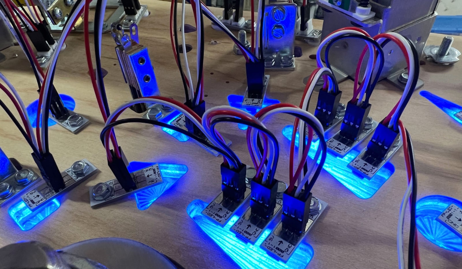
WS2812 LEDs have the three LED elements (red, green, and blue) and microcontroller in a single package. As mentioned above, there are 6 contacts, 3 in and 3 out. In pinball machines, the WS2812 LEDs are mounted to tiny boards with connectors and screw holes, and these are what you screw to your machine.
We sell WS2812 LEDs for playfield inserts, as well as versions for GI (general illumination) which are larger 10mm domes which stick up through the playfield in a manner similar to old school #44 GI bulbs used in classic machines. Both of these types of LEDs are WS2812-compatible 3-wire RGB LEDs, and you can mix and match them in the same chain.
Since the FAST Modern platform supports both 4-wire and 3-wire LEDs, when using 3-wire LEDs, there is no connection to the second pin ("C" clock) on the board headers.
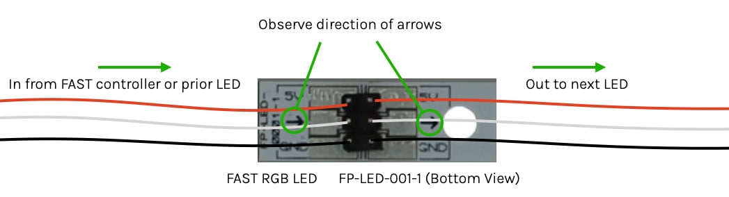
Looking at the WS2812-based LED itself, notice there are arrows showing the "in" and "out" connector directions that must be followed.
The photo below illustrates a real world WS2812-based 3-wire LED chain from an expansion board (also mounted to the playfield).
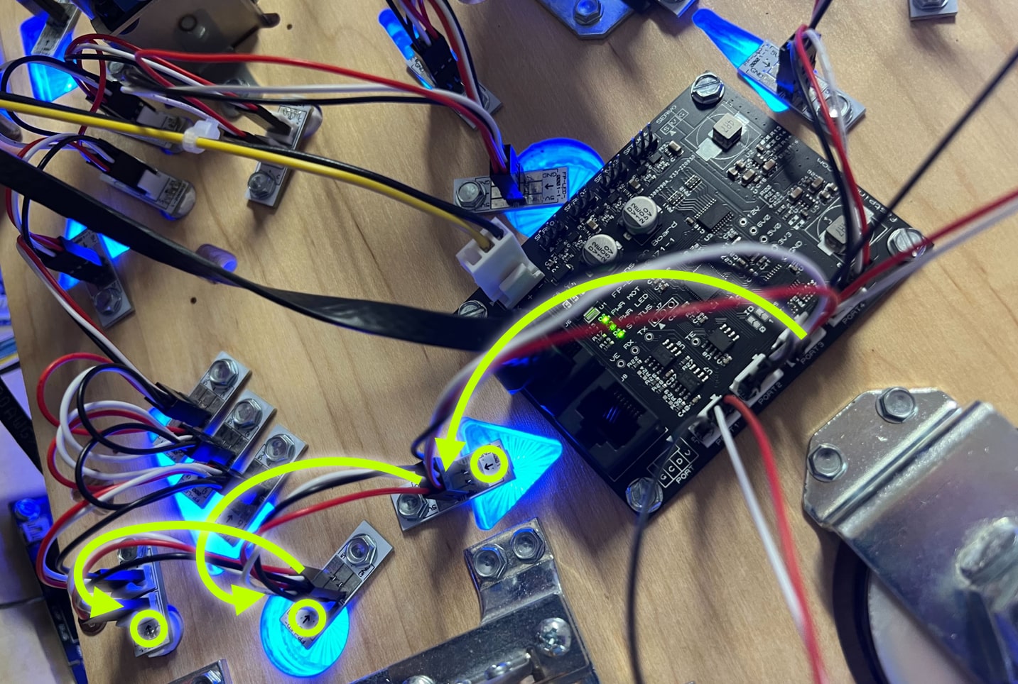
The glowing yellow arrows trace the chain of LED wires from the expansion board port to the first few LEDs, and also circled are the arrows on the LEDs which show which direction the data flows. When you start connecting your LEDs, keep in mind that the wires might cross over each other to get to the proper header, since the LEDs will be facing every which way. (Luckily plugging the chain in backwards doesn't break anything, and seeing a chain not working part way through is likely swapped connectors at that LED.)
Back to that photo, also notice that the third LED in the chain is one of the GI LEDs that sticks up through into the playfield.
Finally, regarding the LEDs you use, you certainly don't have to buy or use FAST LEDs. We make them for convenience, but any WS2812-compatible LED will work. They make Christmas Light versions which some people use for GI, and you can buy the T-10 dome style ones we use in our GI LEDs for direct use. Also, several FAST community members have designed and share all sorts of custom LED boards for pop bumpers, spinning inserts, star posts, stadium lighting, etc. The sky's the limit!
Be mindful of the LED current draw!
Just because you can physically attach up to 128 LEDs doesn't mean you can run them all at 100% full brightness. Similar to the wire gauge and current calculations you do for your coils, power consumption and current draw must be considered when wiring your LEDs too.
FAST expansion and breakout boards which have LED ports can deliver 10W sustained across their 4 LED ports. (So the FP-EXP-0081 which has two banks of 4 LED ports can support 10W per four ports, 20W for the whole board.) But similar to how slow-blow fuses work, the FAST expansion boards will allow more than 10W of LED power for short bursts—as long as 10W is the sustained average. But how much more, and for how long? That's impossible to predict since there are so many variables.
For example, an LED's data sheet might list a maximum current draw of 60mA if all three channels (red, green, and blue) are 100% on full brightness. But real world testing with a meter might reveal LEDs which claim 60mA only actually consume 35-45mA at full brightness.
You also need to consider that an LED at full 100% power might appear to the human eye to be just as bright as one running at 80% power. In this case you'd want to tune your game software to convert a "full on" value to 80%. (In fact the data sheets might caution you against running LEDs at 100% for sustained periods as it significantly shortens their lifespan.)
Another consideration is that the max current consumption (60mA or whatever) would only occur when all three (red, green, and blue) channels are 100%. If you have inserts which are primarily a single color, their full brightness will just use that single channel. (e.g. an RGB on full red might only be 20mA instead of 60mA.) And if you further decide that "full on" is 75%, then a red LED full on might only be 16mA. And if it's mostly flashing (most insert LEDs are not on solid), it might be a "sustained" draw of only 8mA.) Again, testing and experimentation will be your key!
The only LEDs that will most likely be bright and mostly always on solid will be your GI LEDs. But even in those cases, you could opt for RGBW LEDs which would only require a single channel (the white) to be on for most times, meaning they would consume far less than 60mA.
One final thing to keep in mind is that the 10W per 4 LED ports is the sustained average power available. You can exceed that for short periods which might occur with certain lighting effects.
The bottom line is that LED power consumption and brightness is no different than anything else in electronics. Sure, your home stereo goes up to 40, but 25 is super loud and anything over 30 is distorted, so don't turn the volume up over 30. It's the same with LEDs.
Once your LEDs are wired and you start playing with them, you'll see that keeping them within the allowable range is straightforward enough and just another thing you need to keep in balance. If you really do need more power, you can add LED breakouts which will each have their own 10W (coming soon), or you can add an external power supply and bypass the limits of the expansion board power supplies. (This is how things were done in the old days, like with Fadecandys, etc. It requires some real electrical engineering calculations, but if you want a machine to melt peoples' faces off with 500 super bright LEDs, it's definitely possible!)
Do you need additional LED chain power taps?
Alternate section title: Why are the LED chains only 32 LEDs max?
In the current FAST modern platform, the chains of LEDs connected to FAST boards are limited to a maximum of 32 LEDs. (To be clear, that's 32 per LED port, and expansion boards have 4 or 8 of those.) This is a change from the older FAST Nano controller which supported chains of 64, and different than some random RGB LED products you find online which might have chains of 128 or more.
So why does this limitation exist in the latest FAST modern platform? Several reasons.
A big challenge with long chains of LEDs is due to Ohm's law which we discussed with the toxic ground. Since the LEDs are chained one-to-another, the power for the last LED has to go through every other LED before it. All the wire, connectors, joints, components inside the LED, the LED package, etc. add resistance to the chain. More resistance lowers the voltage, so the LEDs further down the chain have progressively lower voltages which ultimately makes them not as bright which causes their color mixes to get weird.
In the previous Nano-based FAST Modern Platform, we told people to add intermediary power taps every 15-20 LEDs. The LEDs run on 5V, so it's easy to just pull some supply lines from the machine's 5V system and they're good to go.
But in Neuron-controlled pinball machines, there is no 5-volt system. This means there's no place to get the 5V from. So, we thought, "Let's just add a 5V power output header to the expansion board for this purpose." Then we thought, "Hey! That takes up the same amount of space as an LED port header. Rather than header for a chain of 64 LEDs and another header next to it for end-of-chain power, let's just add the data pins to the second header and make it two ports of 32 instead of a single of 64."
That said, the real beauty of limiting chains to 32 LEDs is you shouldn't have to deal with adding more power further down a chain. "But wait," you might think, "Didn't you say the recommendation for the prior system was power injection every 15-20, so doesn't that mean we need power at the end of a chain of 32?"
Here's another cool thing about not having the 5-volt system in the pinball machine. Since the 5V for the LEDs is generated locally on the expansion board, the amount of available voltage at the LED port is the full 5 volts.
In the previous generation Nano-controlled machines, the 5 volts came from a 5V power supply, which then had to go through the filter board, the terminal blocks, all the long wiring harnesses, and finally to the LED chains under the playfield. By that point, due to the resistance in the wire and connectors, the "5 volts" was not actually 5V when it entered the LED chain. To make matters worse, LEDs take a lot of power. (128 RGB LEDs on full white use over 7A at 5V which is exceeds the limit of 0.156" connectors.) That massive amount of current also maximized the voltage drop. (Ohm's law math: if resistance is constant, more current means less voltage.)
So when those 5V LEDs got bright, the current draw increased, the source voltage dropped even more, and the LEDs were starved for power. The solution was to add additional power connections at various mid points in the LED chain. Those connections worked because they had less resistance than the path through all the LEDs, so when the current draw increased, the voltage over those wires didn't drop as much.
But in today's world of the Neuron, none of this applies. The expansion boards get 12V of power and generate the 5V the LED chains need right there on the same board as the LED header ports. That 5V really is 5V, and even when the power loads change (LEDs turning on and off, bouncing the current draw), there's still plenty of headroom since the source power is 12V and not 5V.
In Neuron-controlled systems, you shouldn't need to add mid-chain or end-chain power wires for your LEDs. That said, if you do find you need to do this, you can run a wire from the power pins of the expansion board LED port, or the first LED in the chain over to the last one. But you should only do this if you first balance out your chains. No sense struggling to find power for a 32 LED chain if the port next to it is empty. Just split your chain in that case.
Dealing with interference
One of the downsides of serial LEDs is that since a high-frequency digital signal is used to control the colors of all the LEDs in the chain, any EMI or interference on that wire will cause the LED colors to be weird. The easiest way to avoid this is to not run other wires too close and in parallel with your LED signaling lines. This isn't as much of an issue with the current design of the platform, since your expansion boards will be "local" to the area they're used. (e.g. You won't be bundling a bunch of LED lines from your backbox down to your playfield.)
That said, you don't have to get too crazy here, just be aware of what's running alongside each other in parallel. This is one of those situations where it might be easiest to just build and wire your machine and then to see if you have any interference once it's done.
Also if you have other wires that need to cross over your LED control lines, try to make the crossover as close to a 90-degree angle as possible.
What if you want single-color LEDs?
The FAST Controllers only directly support serial RGB LEDs. But what if you need to control single-color LEDs? You have a few options.
Use serial LEDs as single color
If you want to have single-color LEDs in your machine, the easiest way to do this is just to use a serial RGB LED and then to only use one color in your game software. If you're putting that LED under a playfield insert that's colored, you can experiment with the best color setting for the LED to make the insert light up in the color you like. For example, somme people like a red LED shining through a red insert, others like to set the LED to white even though it's shining through a red insert. Just play with it and see. But using serial LEDs will be simpler and cheaper than trying to incorporate a traditional non-serial LED.
Also be aware that WS2812-compatible serial LEDs come in all sorts of packages and form factors (including strands of lights almost like Christmas lights and other wild things). You may thing that you need a traditional LED package for some specific location in your machine, but if you search on Amazon or Ali Express you may find a WS2812-compatible version of that which you can wire into your LED chain like any other.
Wiring traditional (non-serial) LEDs
All that said above, sometimes you will need to wire in a traditional, old-school, non-serial single-color LED. There are a few ways to handle this.
If it's in your cabinet, the FAST cabinet I/O controller has several low-current driver outputs designed for LEDs in the start button and coin door. If you have small LEDs that are always on, you can find 12V ones and wire them into the 12V low current output from the playfield interchange board, or use the FAST 4-channel opto emitter board with traditional LEDs.
Another option is to use a driver board output to control that LED just like any other driver. This might be a good choice if you want simpler single-color LEDs for all your GI and you don't care about dimming or anything.
Another option is to find some WS2812-compatible chip which can be used to drive something else. (All sorts of hacks are available for these types of things.)
Check out the FAST Pinball cookbook
If you want to put all this wiring knowledge to practical use, we have a FAST Pinball Cookbook recipe playfield lower third wiring which walks you step-by-step through wiring an actual playfield (coils, switches, LEDs) to the I/O boards and playfield interchange board. So go check that out if you want to start wiring!
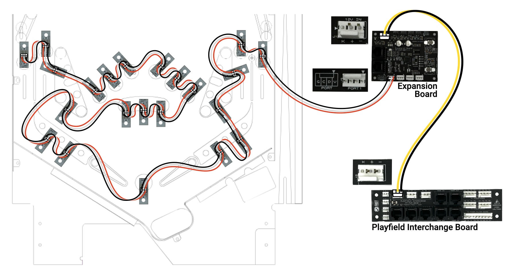
The image above is from the Pinball Cookbook Lower Third Wiring recipe
N or > jump the next page, P or < for previous, search with S or ?