Wiring playfield I/O boards in a FAST Neuron-controlled pinball machine
Wiring, high voltage, and electricity can be dangerous. Read this first!
The voltages and electricity discussed here can be dangerous and could cause property loss or death. It is your responsibility to ensure you are aware of these risks and comfortable with these processes. Furthermore your local jurisdiction may have regulations or rules which differ from what we discuss here, including wiring colors, standards, techniques, etc. Although based on broadly adopted methods, FAST Pinball does not employ Professional Engineers and this information is not professional recommendations. There may be errors, omissions, or typos here. Any pinball machine available to the general public should be reviewed by a licensed Professional Engineer in your region. Use this content at your own risk.
This guide shows you how to wire your FAST playfield I/O boards which is what your switches and drivers connect to. There are three different models of I/O boards, each which support different combinations of switches and drivers.
- FAST I/O 3208 (32 switches, 8 drivers)
- FAST I/O 1616 (16 switches, 16 drivers)
- FAST I/O 0804 (8 switches, 4 drivers)
We also make a special purpose I/O board designed for use in the cabinet (flipper buttons, coin door, etc.) which is covered separately in its own guide after the guides on switch and driver wiring.
You can mix-and-match I/O boards as needed (for a maximum of 9 I/O boards). Most machines will have 2-4 playfield I/O boards, typically mounted vertically under your playfield, located in different areas so they are as close as possible to the things they connect to.
The FAST Modern platform documentation describes how the playfield I/O boards work and provides more background information. Check out that documentation if you haven't yet, since the guide you're reading now focuses more on the actual wiring itself.
Playfield I/O boards work with Neuron and Nano controllers
The FAST playfield I/O boards are compatible with both the FAST Neuron and FAST Nano controllers. However, they use different firmware for each. The FAST controller can upgrade / downgrade the firmware as needed. See our firmware page for details.
FAST playfield I/O boards have three types of wiring connections:
- FAST I/O Loop (covered below)
- Switches (covered in the next guide)
- Drivers (discussed after switches)
FAST I/O Loop wiring
The FAST I/O Loop is a ring network of Ethernet cables that connect the I/O boards to the Neuron. This loop is used to power the I/O boards themselves (via 12V which is delivered via the loop), and handles communications and diagnostics.
Every I/O board has two I/O Loop ports labeled NODE IN and NODE OUT. You connect the "out" from one board into the "in" of the next board, with the final board's "out" going back to the Neuron's node "in" port. You must complete the loop for the I/O boards to function properly.
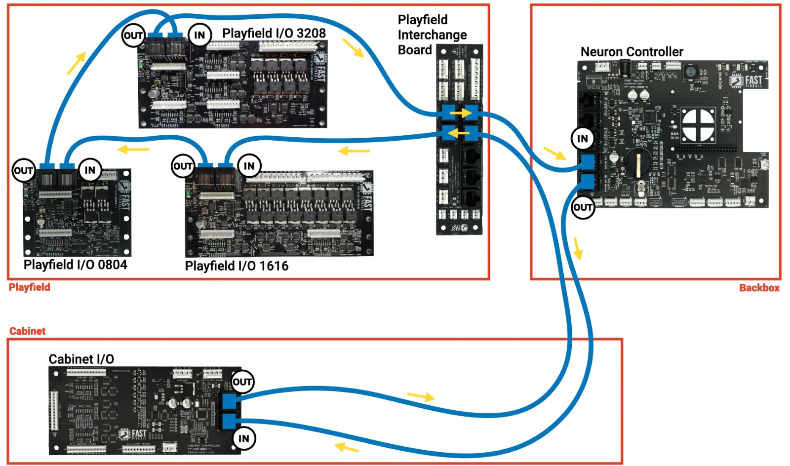
The following diagram shows what this I/O Loop might look like in a machine:
- The Neuron is in the backbox
- Three playfield I/O boards are under the playfield
- The playfield interchange board is at the back of the playfield
- A cabinet I/O board is in the cabinet
I/O Loop wiring tips
- The FAST I/O Loop uses standard computer network (Cat 5 Ethernet) cables. (Cat 5e or Cat 6 are ok too.)
- The FAST I/O Loop is not Ethernet—it just uses Ethernet cables.
- Ensure the OUT from one board connects to the IN of the next board. 99% of problems are accidentally connecting two IN or two OUT ports.
- You must complete the ring / close the loop. Be sure to connect a final cable from the OUT of your last board to the IN of the Neuron.
I/O board order and device numbering
From a technical standpoint, you can connect your I/O boards in whatever order you want. It makes no practical difference in Neuron-controlled machines.
In older FAST Pinball platforms (like the Nano), there were rules dictating which switches and which drivers were connected to which I/O boards, and the first board in the loop had special properties. None of these limitations exist with Neuron-controlled machines, so the order of your I/O boards makes no difference at all, and you can plug any driver and any switch into any I/O board in any order. Yay for flexibility!
The order of I/O boards on the Loop does affect the sequence of how the switches and drivers are presented to the host PC. The following diagram illustrates this:
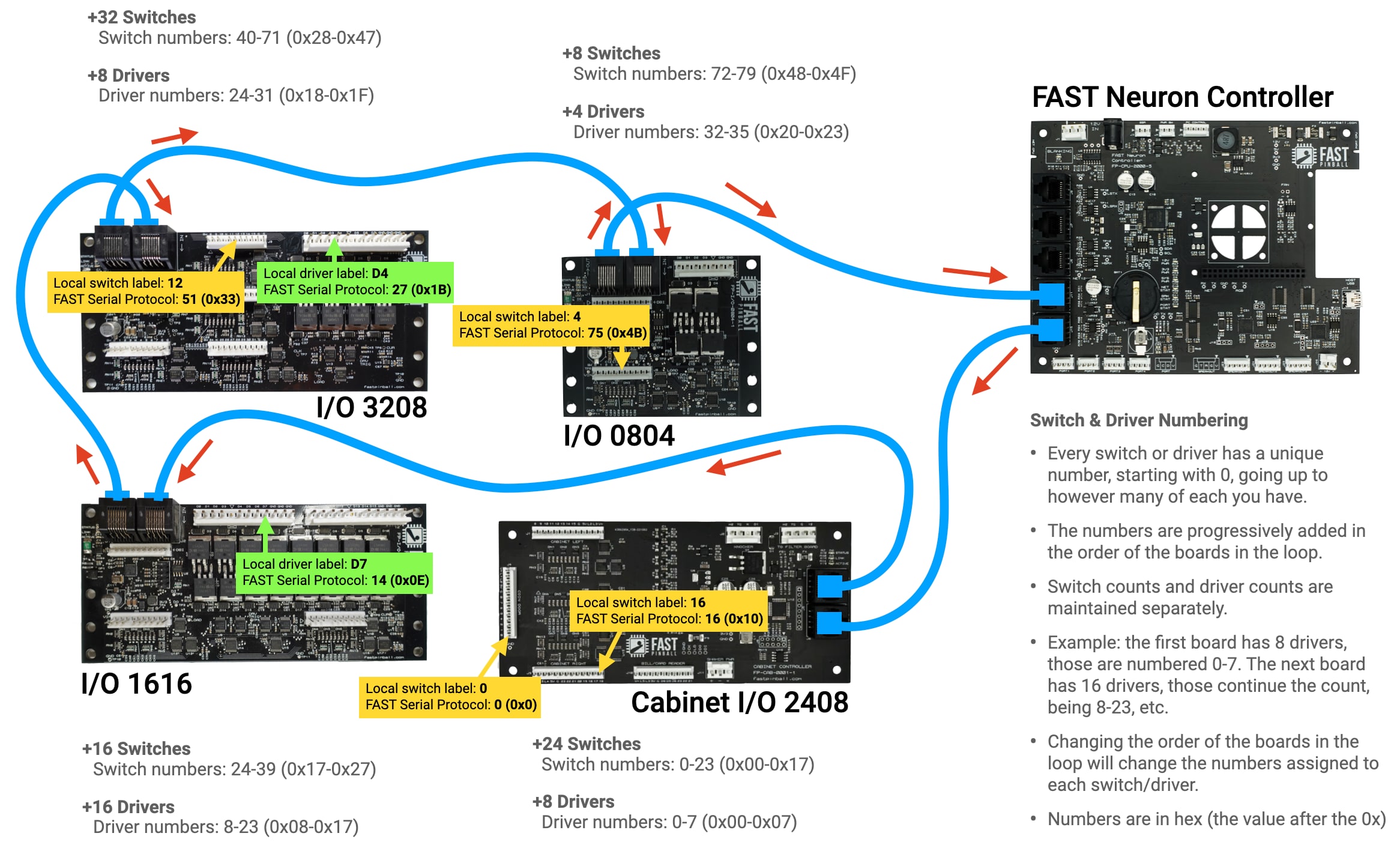
That said, the order does not matter from a practical standpoint. Once you map the switches and drivers to their numbers in your game software, you'll never think about it again. So, again, the order doesn't really matter, just run your I/O Loop in a way that makes the most sense to you.
N or > jump the next page, P or < for previous, search with S or ?