How to wire opto switches & opto switch boards in a FAST Nano-controlled pinball machine
This guide explains how to wire opto switches to your FAST I/O boards. It assumes you've been following our wiring guides, and, since optos are a more complicated version of mechanical switches, it assumes you've read our guide to switch wiring first.
Wiring, high voltage, and electricity can be dangerous. Read this first!
The voltages and electricity discussed here can be dangerous and could cause property loss or death. It is your responsibility to ensure you are aware of these risks and comfortable with these processes. Furthermore your local jurisdiction may have regulations or rules which differ from what we discuss here, including wiring colors, standards, techniques, etc. Although based on broadly adopted methods, FAST Pinball does not employ Professional Engineers and this information is not professional recommendations. There may be errors, omissions, or typos here. Any pinball machine available to the general public should be reviewed by a licensed Professional Engineer in your region. Use this content at your own risk.
This guide is old (for FAST Nano-powered machines only)
This wiring guide is for pinball machines powered by a FAST Nano Controller. If you have a FAST Neuron Controller, please see the Neuron wiring guide.
Opto Basics
Opto switches are a bit more complex than mechanical ones, but still pretty straightforward. An opto switch is made of two parts:
- An infrared LED (called an "IR emitter") that shines a beam towards an IR detector.
- An IR detector which operates like a switch which is "on" when the IR beam is hitting it, and "off" when no infrared light is hitting it.
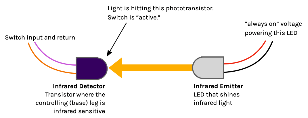
The following drawings illustrate this process. The IR emitter is an LED that's always on, nothing fancy. It's a normal LED except instead of its color being red or blue or green, it's infrared. The IR detector is like a normal transistor, except instead of the base leg being the wire where a little current controls the transistor's "switch" effect, it's a light sensor. That transistor is packaged up as an IR detector by being wrapped in a special translucent plastic that only allows infrared light to pass through. (That's why they look dark purple, like the lens covers on your 1990s VCR.)
When the IR light is hitting the detector, the switch is "on" and reported as active.
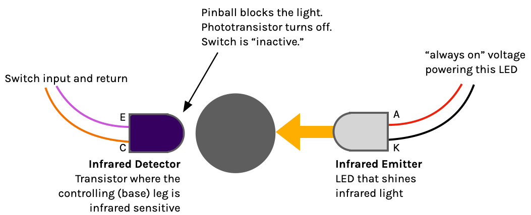
When the IR light does not hit the detector, like when a pinball or plastic tab is blocking it, the switch is "off" and reported as inactive.
One thing about opto switches it that they're backwards / inverted (or "normally closed / NC" as you recall from the previous guide on mechanical switch wiring). So an opto shows as open/inactive when a ball is there or a target is down or a button is pushed, and it shows as closed/active when it's actually not being blocked. This is no problem, as you can configure the switch profile to be NC in the FAST hardware or the switch settings in your software and then treat optos like any other switch.
Wiring optos is also straightforward. Since each opto switch is a paired IR emitter and IR detector, we'll cover the wiring of each of them separately.
Wiring your opto emitters
Opto emitters are just regular LEDs that shine infrared light instead of a color humans can see. Nothing special other than that. They are always on. No pulsing or codes or PWM. Machine on = optos on. Easy peasy.
Of course LEDs come in many shapes and sizes which means infrared LEDs also come in many shapes and sizes. Some are the old-school beefy through-hole designs, and others are teeny-tiny surface mount ones which are attached to little boards. Sometimes you'll wire up a single emitter (like for ramp entry detection), and other times you might have a board with a whole bunch of emitters (like a trough opto emitter board).
As with all LEDs, you need to provide them with the proper voltage so they can consume their correct amount of current. If you just hook up an LED to your 5V power supply it will most like explode instantly. (It's fun, like tiny popcorn.) You need to do some math to calculate the watts and ohms for a resistor to add to the circuit to drop the voltage to a suitable level. And then you need a way to mount that resistor, and ... this is the reason the FAST 4-channel constant current opto emitter board exists:
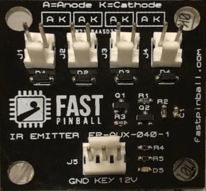
This board takes 12 volts from your 12V bus and then powers up to four IR emitter LEDs. This board is small (about 1.5" square) so you can mount them near your LEDs, and it outputs the proper voltage which it automatically adjusts depending on the LED's current (hence the "constant current"). The output pins are labeled "Anode" and "Cathode" (A or K, yes cathode is abbreviated K) which will match the labeling for the IR LED you're using.
Wiring your opto detectors
While the opto emitters are just IR LEDs, the IR detectors are essentially just switches remotely controlled by IR light. IR detectors are wired like any other switch, directly to one of the 11-pin switch headers on a FAST I/O board.
The only "catch" with IR detector wiring is that polarity matters. You must connect the "Collector" (C) to the numbered switch input (orange wire), and the "Emitter" (E) to the shared switch ground return (purple wire). (If you get this wrong, it probably won't break anything--it just won't work.) Other than that, treat an IR detector like a normal switch. You can use the same daisy-chained purple wire to connect multiple mechanical switches and IR detectors (to the "E" pin). Just remember that both leads of the IR detector must go back to the same I/O board!
As mentioned already, IR detector switches will appear logically inverted, in that they will be active when they are not blocked, and blocking them makes them inactive.
Using third party opto boards
There are several third-party opto boards on the market. Williams and Stern have had several different models over the years, and you can find originals and modern remakes from places like Marco, Pinball Life, Planetary Pinball, etc. Lots of people choose to use these in their machines and often wonder how to wire them.
We'll go through a few examples here and talk about things to look out for.
Single drop target opto board
The first is a single drop target detector board from Stern. There's a U-shaped piece of plastic that holds both the IR emitter and IR detector, so this is an all-in-one unit.
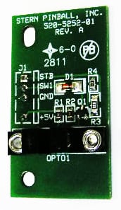
Notice the connector: 4 pins, labeled STB, SW1, GND, +5V. Also notice there are additional components on the board, 4 resistors and a diode, in addition to the opto stuff. This gives us all the information we need to connect this into a modern FAST system:
+5VConnect to the standard 5v power busGNDConnect to the 5v power groundSTBConnect to the I/O board switch header's ground return "G" pin (purple wire)SW1Connect to a numbered switch input on an I/O board (orange wire)
For this Stern opto board, you do NOT need to use the FAST opto emitter board. The FAST emitter board is for powering IR LEDs directly. But in this case, this Stern board is labeled for a raw 5v input (which makes sense since there are those resistors and things to set the current voltage for the LEDs).
NERD FACT
"STB" stands for "strobe" which was the column side of a switch matrix back when this board was created. The columns were powered (strobed) one-by-one, and the processor would read the switch rows active on each strobe.
Single LED emitter and detector boards
These little boards, or ones like them, are still used a lot. Notice there are no components on the board, just the raw IR emitter or collector.
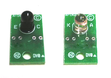
The one with the clear LED is the emitter. (How do we know? First, the clear plastic of the LED is not filtering any light, and second, because the "K" and "A" stand for cathode and anode which are LED emitter labels.)
In this case, YES, you need to use the FAST opto emitter board. Just wire up this emitter to one of the LED output headers on the FAST opto emitter. K to K, A to A. Simple.
For the IR detector side, which we know because the LED is dark purple, filtering out all but infrared light, and the letters E and C are labels used with IR detector transistors.
When wiring this detector to your I/O board, the ground return (purple) wire goes to the emitter (E) pin, and the numbered switch input (orange) wire goes to the collector (C) pin.
Classic trough opto emitter and detector boards
Before we look at this trough opto board, we'd like to point out that we have a FAST Pinball Trough Opto IR board set which is used with a modern trough and is a "drop in" for an existing FAST system. The transmitter side takes 12 volts (it has the opto emitter constant current technology built in), and the receiver side plugs directly into an 11-pin switch header on a FAST I/O board.
So that board is great, but not what we're talking about here. :) Here we have set of boards (one emitter side, one detector side) for a standard trough. This is a 6-ball version, but there are 4-ball versions too.
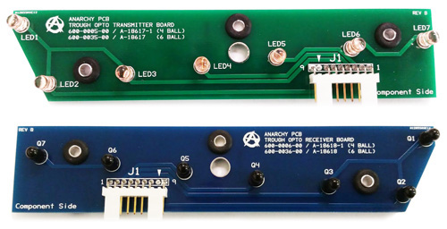
Let's also look at these one board at a time, starting with the emitter (green board) side. It doesn't appear that there are any components on the board, and it also doesn't appear to have labels on the connector. But the traces are pretty big and it's easy to see what this is. It appears to be just IR LEDs connected to a board and a header. So in this case, YES, you would use a FAST opto emitter board. (Actually would would use two since there are seven LEDs.) It's hard to tell from the drawing whether it's common cathode or common anode, but you should be able to figure out with the board in hand and google.
Moving to the detector side, it also appears to be just IR detectors, a board, and a header with straightforward traces. You can look at it to figure out the common pin, which you'd connect to the purple common switch return, and the individual pins corresponding to the seven switch inputs.
Stern 4 bank drop target opto board
Finally, we have another 4-bank drop target board. Hopefully this is an easy one for you by now:
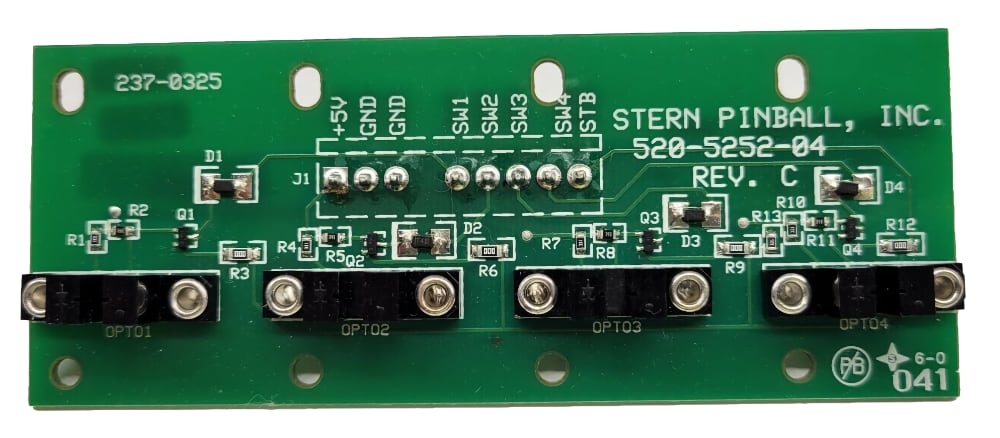
+5VStandard 5v power bus.GND5v power ground.GND5v power ground. (connect both grounds to your 5v ground)SW1I/O board numbered switch input (orange wire)SW2I/O board numbered switch input (orange wire)SW3I/O board numbered switch input (orange wire)SW4I/O board numbered switch input (orange wire)STBI/O board switch return ground (purple wire)
This guide is part of our complete series on wiring your FAST Nano-controlled pinball machine. Click to see the rest!
Wiring guides for FAST Nano-controlled pinball machines
We have many guides and a complete wiring walk-through for your entire pinball machine powered by a FAST Nano Controller. Please read and understand all of the wiring guides before you start planning and physically wiring your machine.
Baseline wiring skills & knowledge
Important wiring and electrical background information you need to know before you start planning your machine's wiring.
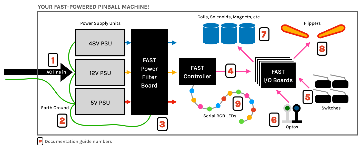
FAST Nano-controlled Pinball machine wiring guides
The guides below walk you through a complete machine wiring, section-by-section. The numbers in the drawing match up to the numbers in each diagram. We assume you follow these in order. Click the image to zoom in.
N or > jump the next page, P or < for previous, search with S or ?