FAST Pinball Neuron Controller: Unboxing & connection tutorial
You just bought a new FAST Pinball Neuron Controller and took it out of the box. Now what? This guide will show you how to connect to it from your computer and send some basic commands.
NOTE: A video version of this tutorial will be added soon
Prerequisites & required hardware
Here's what you need for this tutorial:
- FAST Neuron Controller
- 12-volt power supply (wall wart with 2.1mm barrel connector, or bench supply, details below)
- USB Mini cable which connects to your computer.
- Some kind of computer. (Mac/Windows/Linux/Raspberry Pi -- doesn't matter which)
Step 1: Get to know your Neuron
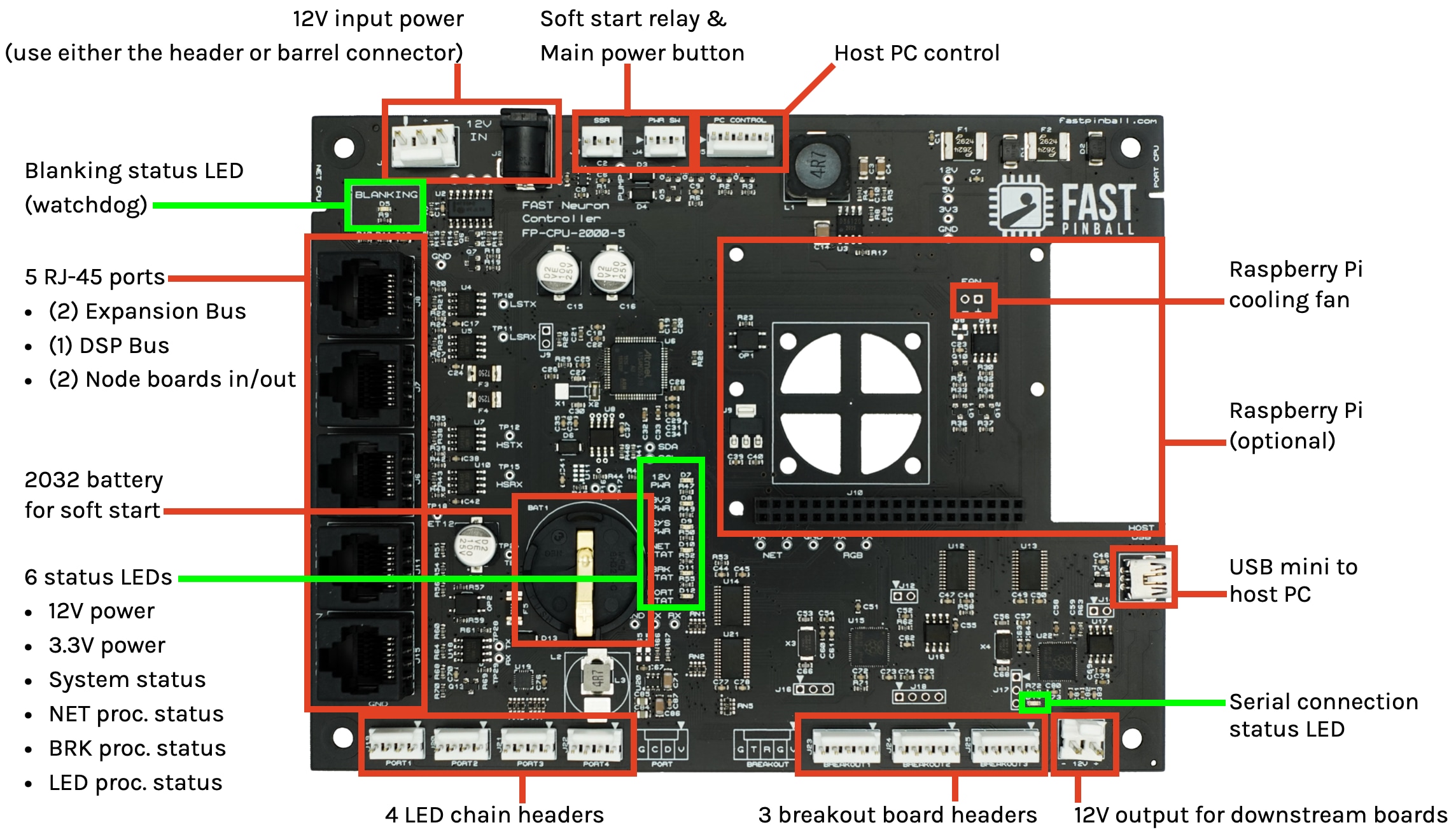
Let's start in the upper left corner and move clockwise around the Neuron
12-volt input power
The Neuron runs on 12 volts. This is the only power required. It's used to power the board itself, as well as the (optional) attached Raspberry Pi and fan, the I/O boards connected to the FAST I/O Loop, any attached breakout boards, and any attached LEDs. Other voltages (such as 5 volts for the LEDs and 3.3 volts for the processors) are generated locally on the Neuron from the 12 volt input power.
There are two options for power input: a 2.1mm barrel connector and a 0.156" connector header. You can use whichever you want. (They are electrically tied together on the board.) Our thinking is that you'll use the barrel connector when you're first playing with the board on your desk, and then you'll switch over the the 0.156" header once you put the Neuron into your pinball machine.
The Neuron and its I/O boards require at least 1.5A (1500ma) of 12V power, though if you have a Raspberry Pi and a lot of LEDs then it could require more, perhaps as much as 5A. (Many more details on the math and how to figure out what you need is covered in the Neuron wiring guide.) But for getting started for now, make sure you have at least 1.5A at 12V. Do not plug other voltages into these ports.
Solid State Relay / Power Switch
These two headers are for use with the Neuron's low-voltage soft power control feature. (Full details are covered in the AC line input wiring guide.)
The SSR header connects to a solid state relay, and the PWR SW header connects to the low voltage power switch in the front of your cabinet.
Host PC Control
This header allows you to connect to the power and reset lines of your host PC, enabling soft power control and gentle shutdown.
Raspberry Pi cooling fan
If you plug a Raspberry Pi into your Neuron, this header allows controls the fan.
Raspberry Pi
If you choose a Raspberry Pi as your host computer, you can plug it directly into the Neuron. See the Raspberry Pi wiring guide for details. Note this is completely optional—you can use any type of computer to power your Neuron-based pinball machine.
Mini USB host PC connection
This is the main USB connection from your host PC to your Neuron. It's used in every case except when a Raspberry Pi is plugged in.
When you connect via USB, three virtual serial ports appear. The three serial ports correspond to the three types of busses the Neuron uses:
- The FAST I/O Loop, connected to FAST I/O Boards for switches & drivers.
- The FAST Expansion Bus, used for LEDs, servos, steppers, etc.
- The FAST DSP Bus, used for segment and DMD displays.
More details on these three ports & how they're used is covered later in this tutorial.
Serial connection status LED
This LED (D14, not otherwise labeled) indicates the status of the host PC serial connection.

 Blinking = Neuron is starting up
- Solid off = Neuron is ready, no host pc is connected
- Solid on = Host PC is connected to a serial port via USB
Note that just plugging in a computer via USB will not cause this LED to turn on. It only turns on when an actual serial connection is active.
12-volt output
This convenience header provides downstream 12 volts which you can use to power another board in your machine. This is limited to 3A sustained / 5A burst and protected by a built in poly fuse.
3 breakout board headers
These headers allow you to plug additional breakout boards directly into the Neuron to control things like servos, steppers, more LEDs, etc. Note that the Neuron is designed to be installed in your backbox, so these headers are meant to be used with breakout boards in your backbox. For breakout boards under your playfield or in a topper, those would connect to local nearby expansion boards.
Also note that if you are using the Smart Power Filter Board, then one of these breakout headers will connect to it for the current monitoring, fuse status, and other "smart" features of the filter board.
4 LED chain headers
These are headers for serial RGB LEDs. WS2812 LEDs are supported today, and a future firmware update will also enable support for APA-102 LEDs. Each port supports up to 32 LEDs. 5V LED power comes from the Neuron, generated from the Neuron's 12V input.
Like the breakouts, these LED ports are designed for LEDs in your backbox. Playfield, topper, or cabinet LEDs will most likely connect to expansion boards nearby.
6 status LEDs
These six green LEDs show the status of the Neuron itself
- 12V PWR The board is receiving 12V input power. Solid on = OK
- 3V3 The board is generating 3.3V power for its own logic. Solid on = OK
- SYS PWR Status of either Raspberry Pi or computer connected to
PC CONTROLheader. Off = OK - NET STAT Status of the NET processor. Blinking = OK
- BRK STAT Status of the processor which controls the onboard expansion & breakouts. Blinking = OK
- PORT STAT Status of the processor which controls the onboard LED ports. Blinking = OK
2032 battery
This battery is used to power the soft power control machine power on process. If you are not using the feature, you do not need to install this battery. (Details on the soft power control option are here.)
5 RJ-45 ports
These five RJ-45 ports are used to communicate with other FAST boards. From top to bottom:
- EXP BUS Expansion Bus output. This is a one-way bus (e.g. not a loop).
- EXP BUS Additional Expansion Bus output. There are two of these for convenience. They are interchangeable.
- DSP BUS DSP Bus output used for things like the segment displays or RGB DMD.
- NODE IN Part of the FAST I/O Loop which is used to connect FAST I/O Boards (Node Boards) This connects from "out" of the last I/O board in your loop.
- NODE OUT FAST I/O Loop out. (Connects to "in" of your first I/O Board.)
Blanking (watchdog) status
- Solid on = Blanking is active / drivers are disabled
- Solid off = Blanking is off / drivers are enabled
This LED shows the status of the Neuron's "blanking" circuit, which is used to shut off high power to the I/O boards. When this LED is solid ON, it means blanking is enabled and drivers are disabled. (e.g. green = safe)
When the Neuron first powers on, this LED will be on, because blanking is enabled and all drivers are disabled. Once a host PC connects and sends a command to disable the watchdog, this LED will turn off. (So when your pinball machine is active and in use, this LED will be off.)
If the watchdog expires, this LED will turn on and the drivers will be disabled.
Step 2: Connect to 12V power
As mentioned in the quick tour above, the Neuron only need a single 12-volt power input to run. It generates all the other voltages it needs from that.
You can use either the barrel jack or the 0.156" header for the 12 volts. (Don't use both at the same time.)
For your initial unboxing and testing, we figure it's easiest to use the barrel connector, and then you can switch to the 0.156" header when you're ready to install the Neuron into your machine.
If you're looking around for a 12V adapter among your junk drawers, make sure you find one with at least 1.5A (1500ma) of power. Also make sure it's 12 volts and not higher or lower.
You can use an adapter that's rated for more than 1.5A (that won't hurt anything, the Neuron will only draw way it needs). The Neuron will draw a max of 5A.
1.5A should be enough to get you started. That can get the Neuron up and running, get a few I/O boards connected (they get their power from the Neuron via the FAST I/O Loop), and provide enough capacity for a few LEDs. If you max out the LEDs (4 ports of 32 LEDs each = 128 LEDs total) and turn them all on full brightness, and plug a Raspberry Pi in, then the Neuron will absolutely take more than 1.5A. But for your initial kitchen table testing, 1.5A should be fine.
When you plug in your Neuron, the LEDs should be in the following states:
SOLID ON
- BLANKING
- 12V PWR
- 3V3 PWR
FLASHING CONTINUOUSLY
- NET STAT
- BRK STAT
- PORT STAT
A FEW FLASHES, THEN OFF
- D14
OFF
- SYS PWR
Step 3: Connect the USB to your computer
Next, connect a cable from the mini USB port on the Neuron to your computer. You can use whatever type of computer you want. We'll show screenshots and specifics for Windows and Mac here, since if you're using Linux you can probably follow along fine. :)
This getting started guide is not written for use with a Raspberry Pi plugged into the Neuron, so if that' your ultimate plan, start with a different computer for now and then we'll switch over to the Raspberry Pi later.
Hopefully it wasn't too hard to find a mini USB cable. Even though micro USB is more popular these days, micro USB is more common these days, that connector is optimized to be small, but it breaks easily and can be finnicky. Since the Neuron is going into a pinball machine which is going to be jostled, shaken, transported, boxed up, shipped, (dropped?), etc., we opted for the more secure and stable connector that mini USB provides. (Once it's in your final machine, you'll use cable ties to secure it even more.)
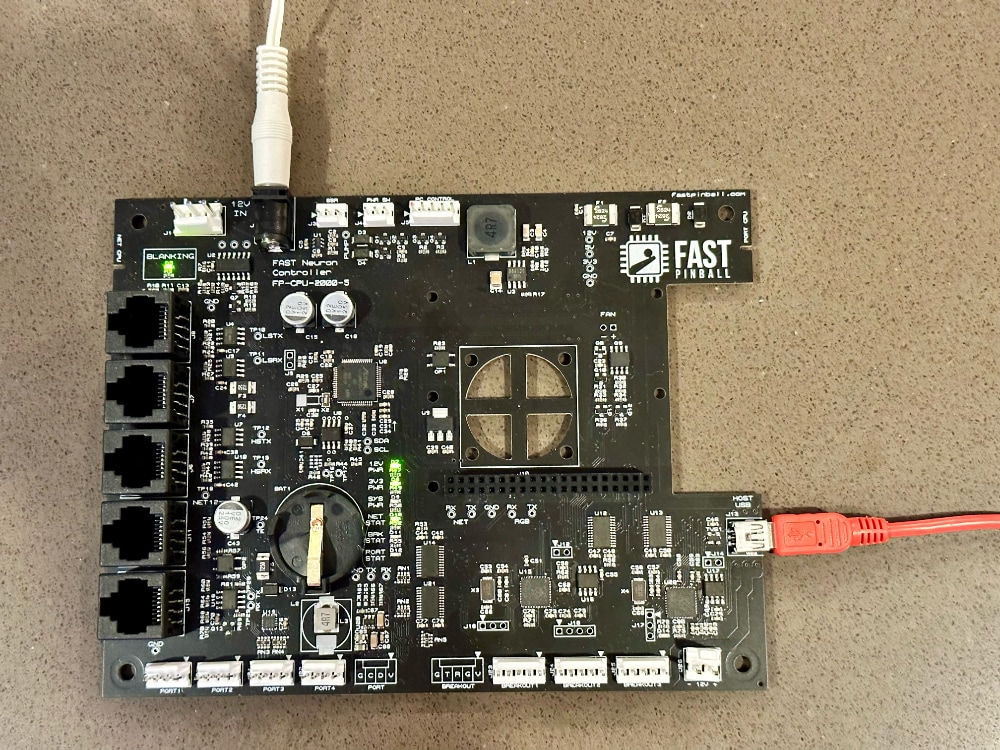
At this point, your project should look something like the photo below. I'm using an 12V wall wart power adapter from an old Netgear network switch, and my mini USB cable is red so I can easily tell it apart from my box of micro USB cables which are all black.
The Neuron does not require any drivers to use it with your computer. When you plug it in, on Mac or Linux you won't even get notified of anything. On Windows you'll see a popup letting you know that a new device was found.
Click the "Mac" or "Windows" tab below to see screenshots and notes for your specific platform.
On a Mac, you should sew a new device, "Neuron Controller" in the USB section of the System Information tool.
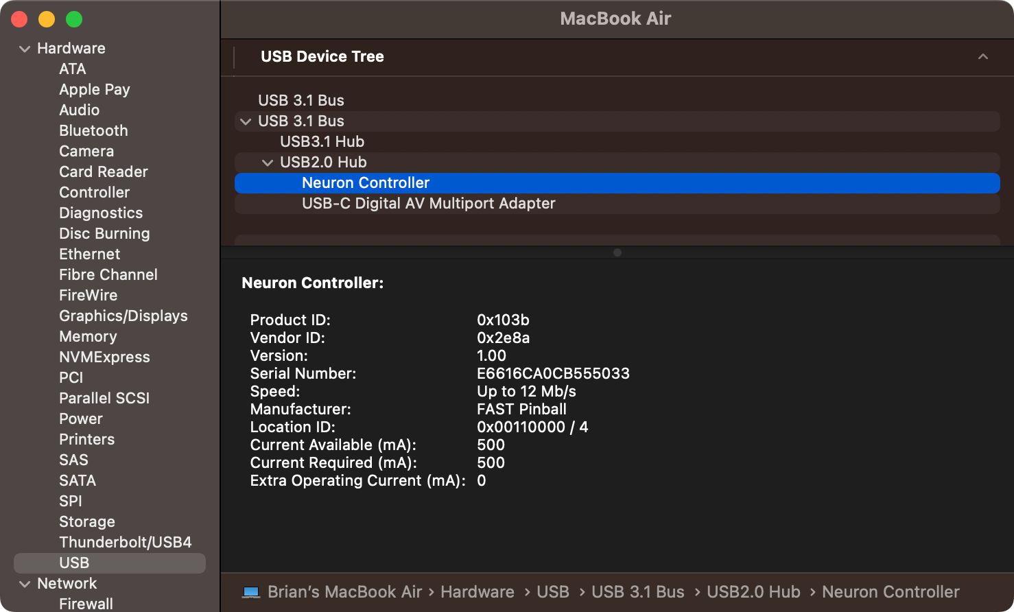
You will also see three new serial ports appear, most likely named:
/dev/tty.usbmodem1101/dev/tty.usbmodem1103/dev/tty.usbmodem1105
(If you don't know what this means or how to find these, that's fine for now.)
Coming soon! The ports on Windows will most likely be something like:
COM3COM4COM5
But your exact port numbers might be different depending on your specific computer.
Step 4. Get a terminal emulator app
Your computer will communicate with the Neuron via the three virtual serial ports. (We call these "virtual" serial ports because the actual communication is of course USB, but USB can be complicated and requires hardware drivers and things like that, whereas communicating via serial ports is simple. So we make the Neuron look like serial ports even though it's really USB. Cool!)
For this initial testing, you can download a program called a terminal emulator which will let you connect to the Neuron and type messages to it to do different things, and to receive messages back from it. That's what we're going to do now!
To be very clear, this is NOT how you're going to use your Neuron ordinarily moving forward. You will run pinball software (such as the Mission Pinball Framework) on your computer and then that pinball software will do this terminal serial communication really fast in the background. But for now, we'll use this terminal software manually so you can see your Neuron in action!
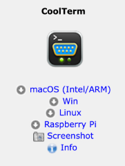
You can use any serial terminal emulation software you want, so if you have a favorite, go for it. If you have no idea what "Terminal Emulation Software" even is, no prob! You can download one and follow along. We like one called "CoolTerm" because it's free, easy to use, and there are versions for Mac, Windows, and Linux.
Download and install CoolTerm to follow along here. If you're using a different terminal emulator, just configure it for the same settings we discuss here.
The website for CoolTerm is pretty old school. Look for the download links like the screenshot on the left. At the time of this writing, version 2.0.0 is the latest.
Step 5. Configure CoolTerm
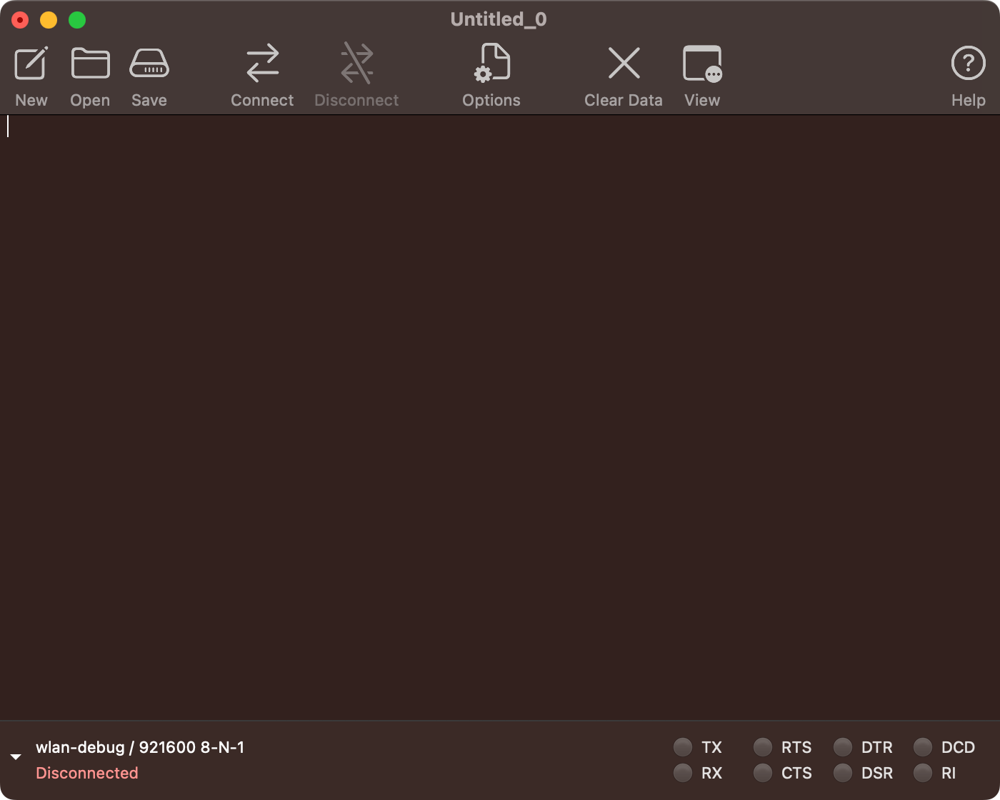
When you open CoolTerm, you will see an empty window. (If you're on a Mac you'll need to find the CoolTerm app and right-click and choose "Open" to get around the system restrictions on non App Store software.)
We are just going to show screenshots taken from a Mac, but if you're on Windows or Linux, it should look similar enough for you to follow along. When you launch CoolTerm, it will look something like this:
Before you can connect to your Neuron, you'll need to configure a few options. Click the "Options" icon from the toolbar which will open this configuration screen:
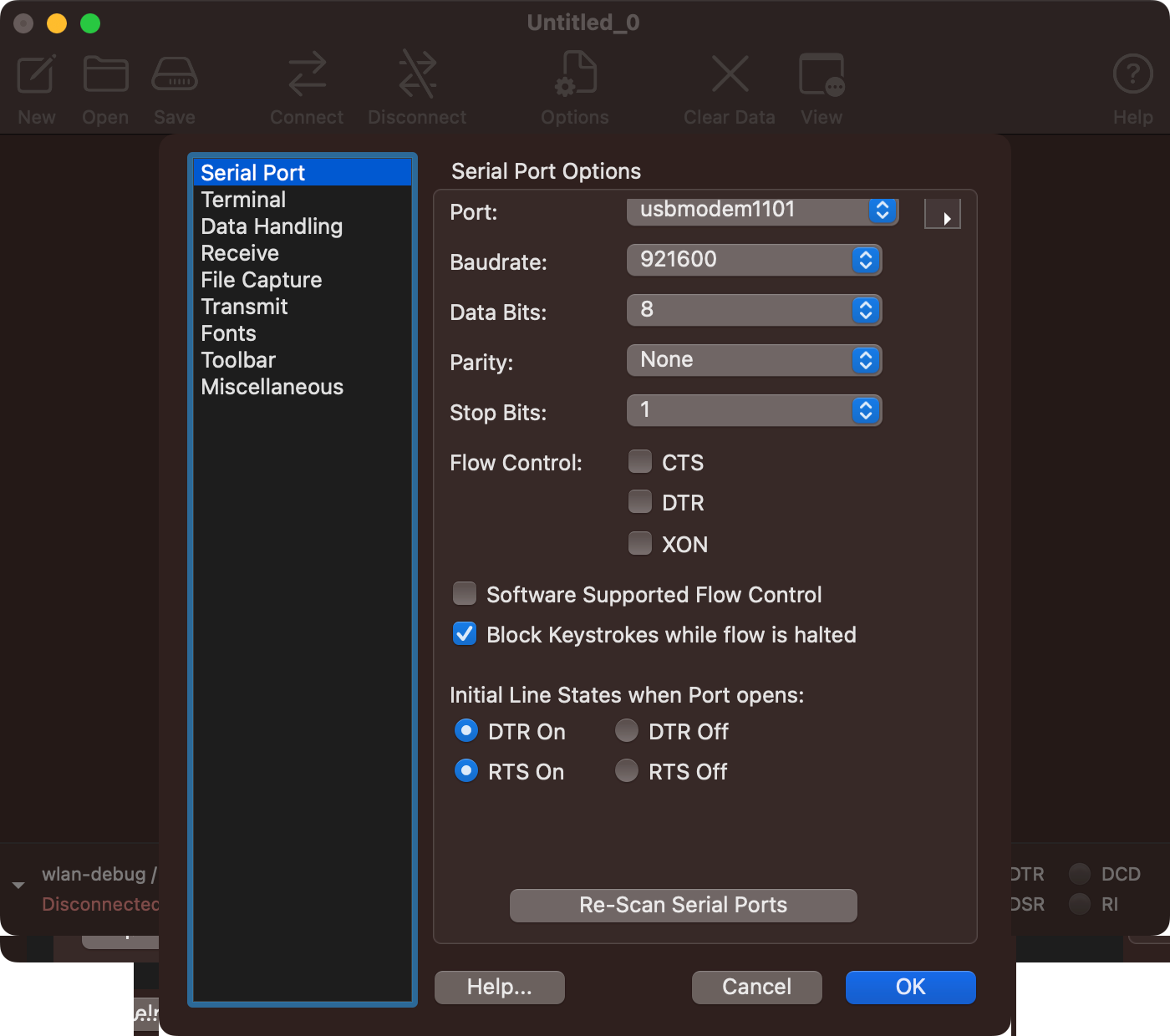
On the "Serial Port" page, you'll see a "Port:" section with a drop-down list of serial ports. Click that and you should see the three serial ports from the FAST Neuron controller. (On Mac this will most likely be called usbmodem1101. On Windows it will be something like COM3.)
The three serial ports correspond to the different subsystems on the Neuron. The first is for the "NET" processor which handles I/O board communications for switches and drivers. The second is for the Expansion Bus which talks to Expansion boards for LEDs, servos, steppers, and other devices. The third is the DSP Bus which is used for segment displays or a DMD.
If you don't see any ports like this, make sure your Neuron is powered on and connected to your computer, then click the "Re-Scan Serial Ports" button. If you don't know which ports are from your Neuron, just turn the Neuron off, re-scan the ports, then turn it on and re-scan again and pay attention to which three new ports just appeared.
For this tutorial, select the first port (in numerical order) from the three Neuron ports. (Note your ports might not show up on the list in numeric order. For some reason on my computer, they are in the order 1101, 1105, 1103. Who knows why? For this step, you want to pick the first one numerically (the lowest number of the three), not necessarily the one that is first on your list.
Next, click the "Baudrate" dropdown box:
- Select "Custom..."
- Enter
921600
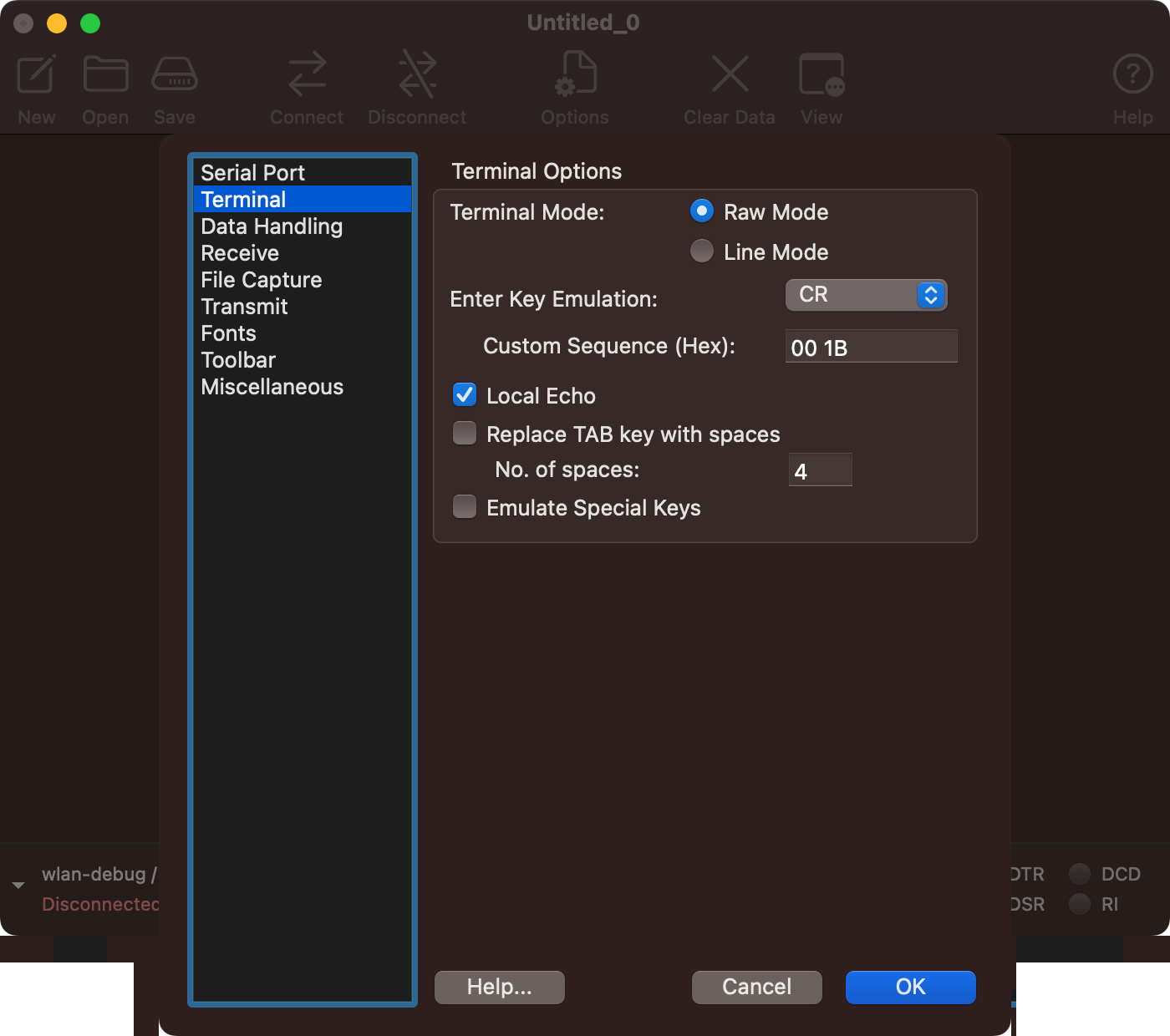
Next, click on the "Terminal" section in the left-side pane.
- Terminal Mode should be
Raw Mode - Change the Enter Key Emulation to just
CR - Check the box to enable Local Echo
Your terminal options should look like this:
The settings, in summary:
- Three new serial ports show up when you connect the Neuron. Select the first one (in numeric order) from the list.
- Serial Port settings: Baudrate
921600, Data bits8, ParityNone, Stop Bits1. - Terminal settings: Terminal Mode:
Raw Mode, Enter Key EmulationCR, Local Echo:Checked (Yes)
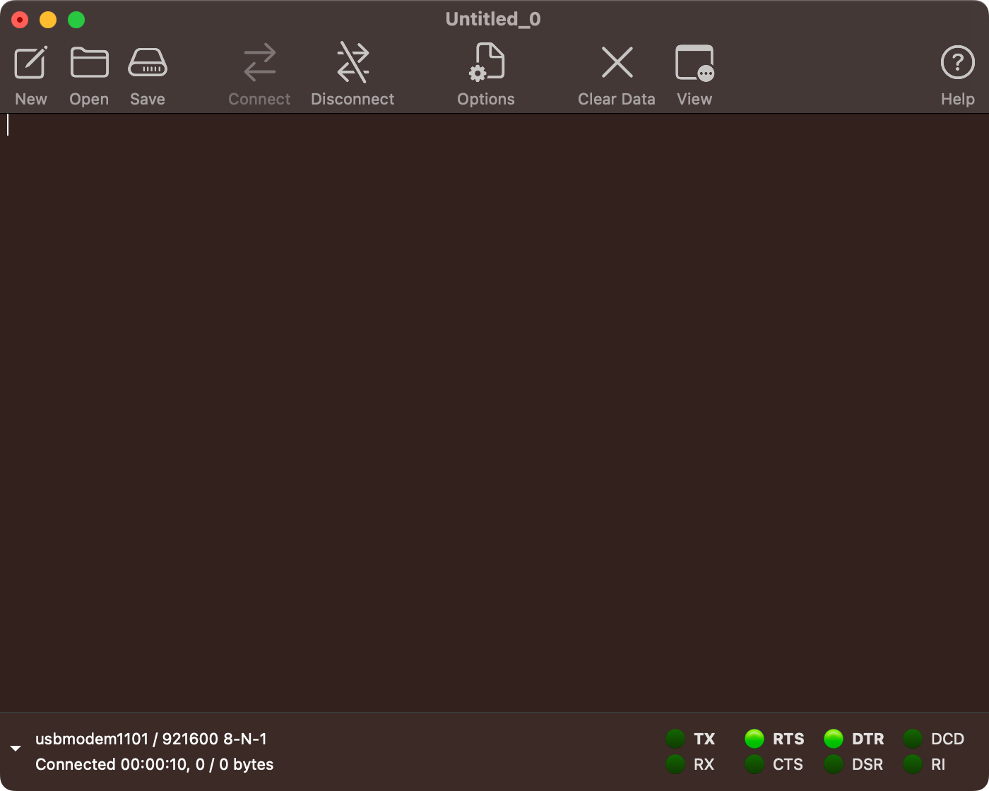
At this point you are ready to connect. Click the "Connect" button in the toolbar. Aaaaannnddd.... Well, it looks like nothing happens! But you should be connected!
On your Neuron, you should see LED D14 turn on. (That's the LED right above Breakout 3 near-ish to where the USB plug is connected. It will turn on when your serial software is connected and off when you disconnect.
In CoolTerm, you'll notice it says "Connected" in the lower left corner and a timer is running, and some of the status "lights" in the lower right corner are green.
You can verify the port name and settings via the lower-left corner. In the screenshot below it shows we're connected to port usbmodem1101 / 921600 8-N-1:
Step 6. Send some commands to the Neuron
Now you have an interactive terminal you can use to talk to the FAST Neuron Controller. You can send commands and see results in real time. For example, let's verify the ID of the Neuron. To do this, type id: and hit Enter. You should get a response back similar-ish to this:
id:
ID:NET FP-CPU-2000  02.13
A full explanation of what all this means is below.
If you mistype this command, you might get some strange responses that end in :F. This just means the command failed. No big deal, just try again. (The same will happen if you just hit the enter key by itself. You'll get an XX:F response since enter by itself is not a valid command, but again, that's fine, just try id: + Enter again.)
If you don't get a response, or your response doesn't start with ID:NET, that means you selected the wrong serial port. You want the numerically first port in your list, and note the list of ports may not show in order on your computer.
Once you confirm that you get a response like the one above, there are four pieces of information useful to you:
ID:This is telling you what type of response this is. Most responses match the command that was sent. (e.g. you sendID:, the response comes back starting withID:)NET:You are connected to the "NET" processor of the Neuron (which is the one connected to the first of the three virtual serial ports). The NET processor is responsible for communicating with the FAST I/O boards over the FAST I/O Loop.FP-CPU-2000is the product ID (the part number) of the board you're connected to. FP-CPU-2000 is a Neuron. You can use the part number index if you want to see the part number for what you're connected to.02.13is the firmware version that the processor you're connected to is running.
Step 7. Confirm / update your firmware
While you're connecting to your hardware for the first time, you should probably verify you're running the
Getting switch events from connected I/O boards
Coming soon!
This section of the documentation is not yet complete and will be coming soon. However, if you need this now, and/or you want to share what documentation is most important to you, please post to the #docs channel in the FAST Pinball Slack community. Thanks!
We plan to write a more complete tutorial on this in the future, but for now, if you connect your I/O Loop to FAST I/O boards and want to receive switch events in the serial terminal, you need to first enable interactive switch reporting via the following command: ch:2000,1.
ch:2000,1
CH:P
Troubleshooting
What if you can't connect to your Neuron? Verify the following:
- Is the Neuron receiving power? There should be a several LEDs either on or flashing.
- Is the Neuron connected to your computer via USB?
- Did you select the proper serial port? It should be the lowest numerically of the three that show up.
- Did you set the baud rate to
921600? - Did you configure the other terminal settings, specifically Local Echo and that the Enter key sends
CR? - Did you actually hit the "connect" button in the toolbar and connect?
If you're still stuck, reach out to us and we'll help (and update this doc!)
What is this XX:F stuff?
You might notice some other random messages on your terminal screen. Any response you get from the Neuron that ends in an :F is telling you that the command failed. This usually means you typed in a command that was not valid.
So for example, if you type hello Enter, you'll get an XX:F command which is telling you the command was not recognized and failed. It will look like this:
hello
XX:F
If you just hit Enter without any command, you'll get an XX:F since you're sending blank commands which are not valid. You might get other types of responses depending on the letters of what you send. The bottom line is that anything that ends in :F failed. You can just type the id: command again at any time.
hello
XX:F
id:
ID:NET FP-CPU-2000  02.13
But now you're connected! It's very boring, but functional.
Are you using MPF? Check out our template config files!
If you're planning to use MPF, we have a repo which has FAST Neuron Controller template config files for MPF. These are pre-configured to work with the Neuron and will get you up and running quickly which will let you verify you have MPF installed properly and it can connect to your hardware. You can find them here.
Next up: wiring your playfield's lower third
We have a pinball cookbook recipe for wiring the lower third of your playfield].
N or > jump the next page, P or < for previous, search with S or ?