How to wire your Power Filter Board in a FAST Nano-controlled pinball machine
Wiring, high voltage, and electricity can be dangerous. Read this first!
The voltages and electricity discussed here can be dangerous and could cause property loss or death. It is your responsibility to ensure you are aware of these risks and comfortable with these processes. Furthermore your local jurisdiction may have regulations or rules which differ from what we discuss here, including wiring colors, standards, techniques, etc. Although based on broadly adopted methods, FAST Pinball does not employ Professional Engineers and this information is not professional recommendations. There may be errors, omissions, or typos here. Any pinball machine available to the general public should be reviewed by a licensed Professional Engineer in your region. Use this content at your own risk.
This guide is old (for FAST Nano-powered machines only)
This wiring guide is for pinball machines powered by a FAST Nano Controller. If you have a FAST Neuron Controller, please see the Neuron wiring guide.
This guide continues our step-by-step pinball machine wiring guide and focuses on the FAST Power Filter Board wiring.
Before you read this guide, you should read these others first:
By this point, you should have also read our other guides on AC power wiring, power supplies, and earth ground. Now you're ready to wire the DC outputs of your power supplies to the FAST Power Filter Board, and to figure out your power transmission strategy for your machine.
Let's start by looking at the FAST Power Filter board for 48, 12, and 5-volt machines. You can refer to the product manual for details, including more explanations of features, full pinouts, schematics, etc. The wiring guide you're reading now is more focused on how to integrate the FAST Power Filter Board into your machine versus the specifics of the board. You can follow along with the diagram below. (Click to zoom in.)

Understanding the FAST Power Filter Board
The FAST Power Filter Board is the interface between your power supplies and the rest of your machine. It serves a few specific purposes conveniently wrapped into a single board:
- Three large capacitors maintain the voltage on your high-voltage lines when lots of high-current coils are driven at the same time. (Flippers and magnets, mostly.)
- A ground tie point for all the DC grounds in your machine.
- Holds 6x30mm fuses (with LEDs to show at a glance which fuses are good.)
- Has a switch input to disable the high-voltage circuits. (Typically wired to the coin door switch to cut off high power when the door is open).
This board supports five independent DC power supply lines: 48V, 12V, and 5V, plus one additional high voltage and one additional low voltage line. Each of these five DC power supply lines is independently fused. (See the guide to fuses for details on fuse value selection.)
Power supply to filter board connections
The first connector we'll look at is the INPUT connector on the power filter board. This is a 12-pin, 0.156" header, so you'll need to get a 12-pin, 0.156" female connector housing and pins to make it. Make a custom cable with the 12-pin female connector on one end for the filter board input and then fork spade connectors crimped to the wires on the other end to connect to your power supply DC outputs. We also highly suggest that you buy the key plugs (to stick in the female connector pin location which corresponds to the missing pin on the board's header). Since the key plugs are in different locations on each connector, this will help ensure you (or someone else) doesn't plug the wrong connector into the wrong header.

Why are there (2) HV+ and (2) 5V input connections?
Remember from the intro guide to grounding that wires are just really long and bendy resistors, and also that when you have high current moving over resistance, the result is a voltage drop. Since the current required to fire a coil is fixed, you can minimize the voltage drop by minimizing resistance. In electrical theory, connecting two of the same value resistors in parallel cuts the resistance in half, meaning that running two +48V wires from your PSU to your filter board will cut that resistance in half which helps to minimize the voltage drop and ground rise when high current coils are firing. (More details on this are in upcoming sections on power distribution and coil wiring.)
The same is true for the 5V line. If you have a lot of LEDs, all of them on at once could draw a lot of current (similar to a high-current coil, except on the 5V DC power line), so you have the option to double up the +5V connection there too in order to minimize the resistance and associated voltage drop.
Note that in the diagram above, the PSU on the left only has one screw terminal for the +5V DC (+V1). Since the screw terminal itself is beefy and low resistance and probably supports 15A, you can simply run a second 5V wire from that same terminal (give the second wire its own spade connector though) and then to the other 5V pin on the 12-pin connector.
Is +48V DC your only high voltage? Combine HV and V1 to get three caps!
The FAST Power Filter Board has three large capacitors. If you look at the board's block diagram in the product manual, you'll see that two of those capacitors are connected to the HV+ line, and one is connected to the V1 line. This lets you have multiple high-voltage lines, like if you have some coil that needs 24V DC instead of 48V or something.
But if 48V DC is your only high-voltage need, then you should (really, yes, always!) connect the +48V DC from your power supply to both the +HV lines and the V1 line on your power filter board, like this:

Why? Because when you do that, all three capacitors will be used to provide extra power when needed on your +48V DC line. It's like getting one extra cap for free! (And those caps are expensive, you already have it on the board, so use it!)
If your power supply doesn't have enough screw terminals or outputs, you can connect multiple wires to the same terminal, or go through a terminal strip or use lever wire connectors.
Why are there so many ground wires?
There are multiple ground pins for the same reason as the multiple HV+ and 5V pins. Resistance in wires complicates things in high-current situations, and since running multiple wires in parallel lowers the overall resistance, you want to run as many ground wires as you can. (Really you can't run too many. Practically, sure, you'll get to a point where additional ones don't matter, but if you're ever on the fence about running another ground wire, just do it!)
Power distribution from your filter board to your machine
In a smaller or simpler machine, you can build another cable similar to your input one which would connect to the filter board's OUTPUT connector and then provide the various voltages where you need them. (This is covered in upcoming sections, but would include things like 12V and 5V to your Nano controller, 12V to any opto emitter boards or the trough emitter board, etc.) However in most practical cases, you'll probably have so many connections needed to all of your DC voltages (and their grounds) that you'll end up using multiple terminal strips to act as distribution points for your various voltages and ground zero point. This topic is important enough that it has its own guide (More Power!) which we suggest reading last to bring everything together after you read through the remaining wiring guides.
Switch connections to the power filter board
The FAST Power Filter Board has two 0.100" switch headers.
Header J2 is used to connect a switch which enables the high-power output of the filter board. This is simple. When J2 pins 1 and 3 are connected, high power flows. When they are not connected, high power is cut off. There's an LED labeled "ENABLED" next to it which shows at a glance if that switch is open or closed.
The purpose of this switch is to be connected to the coin door switch so the machine shuts off high power when the coin door is open. When the switch on J2 is open, power is interrupted on the HV+ and V1 power lines, but 12V, 5V, and V2 stay active. What's cool about this switch is that it's low voltage, meaning you don't have to run a high voltage line to the front of the cabinet like in the old days.
When you're testing your machine, or just getting set up on your workbench, if you're not getting high voltage out of your filter board, it's probably because you don't have a switch connected to J2 pins 1 and 3. Just hook a jumper across them or wrap some wire around those pins for now. (If you jumpered J2 and still don't have high power, don't forget you need to install a fuse too.)
The second switch header, J1, is a switch output which mirrors the state of the filter board's high voltage enabled status. So you use J1 just like any other switch in your machine and connect it up to a switch input on one of your I/O boards. Then when the high voltage is enabled, the filter board closes the connection between J1 pins 1 and 2. What your machine code does with that switch is up to you. Maybe you put that message on the display that high power is disabled because the coin door is open. Maybe you enable a ball save so the same player gets their ball back when you close the door. Maybe you pause all timers? Etc.
So, in summary, the coin door switch is connected to J2, then J1 is connected to your I/O board switch input, and you have nice control over your high power using just safe low power.
This guide is part of our complete series on wiring your FAST Nano-controlled pinball machine. Click to see the rest!
Wiring guides for FAST Nano-controlled pinball machines
We have many guides and a complete wiring walk-through for your entire pinball machine powered by a FAST Nano Controller. Please read and understand all of the wiring guides before you start planning and physically wiring your machine.
Baseline wiring skills & knowledge
Important wiring and electrical background information you need to know before you start planning your machine's wiring.
FAST Nano-controlled Pinball machine wiring guides
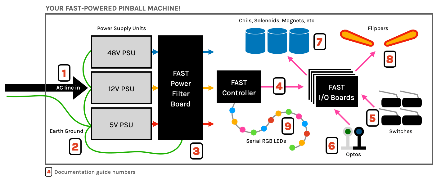
The guides below walk you through a complete machine wiring, section-by-section. The numbers in the drawing match up to the numbers in each diagram. We assume you follow these in order. Click the image to zoom in.
N or > jump the next page, P or < for previous, search with S or ?