Wiring serial RGB LEDs in a FAST Nano-controlled pinball machine
Wiring, high voltage, and electricity can be dangerous. Read this first!
The voltages and electricity discussed here can be dangerous and could cause property loss or death. It is your responsibility to ensure you are aware of these risks and comfortable with these processes. Furthermore your local jurisdiction may have regulations or rules which differ from what we discuss here, including wiring colors, standards, techniques, etc. Although based on broadly adopted methods, FAST Pinball does not employ Professional Engineers and this information is not professional recommendations. There may be errors, omissions, or typos here. Any pinball machine available to the general public should be reviewed by a licensed Professional Engineer in your region. Use this content at your own risk.
This guide is old (for FAST Nano-powered machines only)
This wiring guide is for pinball machines powered by a FAST Nano Controller. If you have a FAST Neuron Controller, please see the Neuron wiring guide.
This guide shows you how to wire up LEDs which are controlled via your FAST Pinball controller. In modern machines, most (if not all) LEDs are RGB (meaning the software controls the color and brightness), and these LEDs are used for just about everything nowadays, including things that in the past were flashers and GI (general illumination).
Understanding Serial RGB LEDs
The first step to wiring your LEDs is to understand how they work. The types of LEDs that FAST Pinball controllers support are referred to as "serial LEDs" or "addressable LEDs". Specifically the type of LED is called "WS2812" (which is the part number of the original company who made them, though now they're available everywhere as that.)
Serial LEDs have six pins: three in and three out. The in pins are +5V, ground, and a serial data in, and the out pins are +5V out, ground, and serial data out. Each LED has a tiny microcontroller in it plus a red, green, and blue LED element, and you connect your LEDs in long chains. Each LED reads its own values from the serial line and also passes the data from the serial line down to the next LED. The LED controller (the FAST board, in this case) sends the instructions for every LED in the chain out the single serial pin.
Much much much much more has been written on the internet about serial / addressable LEDs. So rather than rehashing all that here, if you'd like to learn more, we like this guide from DeRun Lighting which is essentially "Addressable LEDs 101". If you're new to these types of LEDs, read it here. FAST Pinball controllers only support WS2812 LEDs and that guide covers several other styles too, but the core concepts apply, and the link is a great primer including showing examples and explaining things like voltage drop which is a important in pinball machine LED lighting.
Connecting LED chains to your FAST Controller
The FAST Nano has four, 3-pin headers for connecting chains of serial RGB LEDs. Each header (called a "channel") supports up to 64 LEDs. The LEDs are numbered in sequence as shown in the diagram below. (Click to zoom)
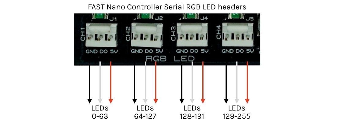
You do not have to put 64 LEDs on each channel, and the number of LEDs per channel does not affect the numbering. (For example, if you had 10 LEDs on Channel 1, they would be numbered 0-9, and then if you had 20 LEDs on Channel 2, they would be 64-83, and you wouldn't have any LEDs numbered 10-63.)
The distribution of LEDs across channels does not affect performance. It really doesn't matter if you put 60 LEDs on one channel or across all four. Just wire them based on convenience. (You'll have to add more power lines for longer chains, but that's easy enough to do and covered in a bit.)
The Nano gets the 5V to power the LEDs from the +5V pins on its power header. If you have more than 100 LEDs or so (more than about a 3.5A draw), then you should run two +5V red wires to the Nano, and two black ground wires back to your ground tie point. Otherwise one red and one black (and one yellow +12V) to the Nano's power header is fine. (See the cabinet wiring guide for details.)
Wiring the LEDs
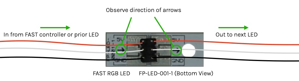
The WS2812 LEDs have the three LED elements and microcontroller in a single package. As mentioned above, there are 6 contacts, 3 in and 3 out. You need to attach the LED packages to a board in order to use them. We sell versions of these designed for playfield inserts which have the WS2812 package pre-soldered to a tiny board which you can solder the wires to directly, or where you can solder a 6-pin (2x3) 0.100" header which you can use with plug-in wires. The diagram below shows the underside of a FAST RGB insert LED with the header attached, and how the wires connect. Note the arrows because the "in" and "out" connector directions must be followed.
You don't have to use the FAST LED insert boards. You could buy raw WS2812 chips and design your own light boards, or use WS2812-style controller chips with your own LEDs, or use other format LEDs (T-5 package, for example) with external chips, etc.
Whether you use connectors or solder the wires on directly doesn't really matter. Connectors do add more resistance versus soldering wires directly, and the resistance of long LED chains adds up to a decent voltage drop which will require additional power feeds, so maybe you need more power feeds when using connectors versus soldering, but many people feel the trade-off for the convenience of connectors (especially when replacing a bad LED) is worth a few extra power taps.
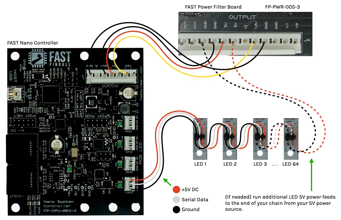
The diagram below shows how your chains of serial LEDs should be wired and attached to the FAST Controller. Also shown is the option for the additional power feed at the end of the LED chain. (More on this in the next section.)
Dealing with power sags / voltage drop
The WS2812 LEDs run on 5 volts. If you give an LED less than 5V, it will be dimmer. This creates a discoloration effect in an RGB LED since the different chemistry for the red, blue, and green LED elements cause them to require different amounts of power, which means that when the voltage drops, each color channel dims at a different rate, meaning that in addition to getting dimmer, your colors will actually start to look weird.
As we've mentioned several times in these wiring guides already, this is due to Ohm's law. LED chains have lots of transitions (wire, connectors, chips, solder joints,) so there's a lot of resistance which causes the voltage to drop for a constant current, and since the LEDs are only 5V to begin with, it doesn't take much of a drop to start to be noticeable. (And the brighter you run your LEDs, the more current they'll require, which will lead to a higher voltage drop since the resistance is constant.) ((Oh, and when the wire heats up, resistance also increases, which leads to more voltage drop.))
This doesn't mean that serial LEDs are bad or not appropriate for a pinball machine, rather, it measn that you need to wire them properly, which is almost definitely going to include injecting additional +5V and ground at additional points in a LED chain.
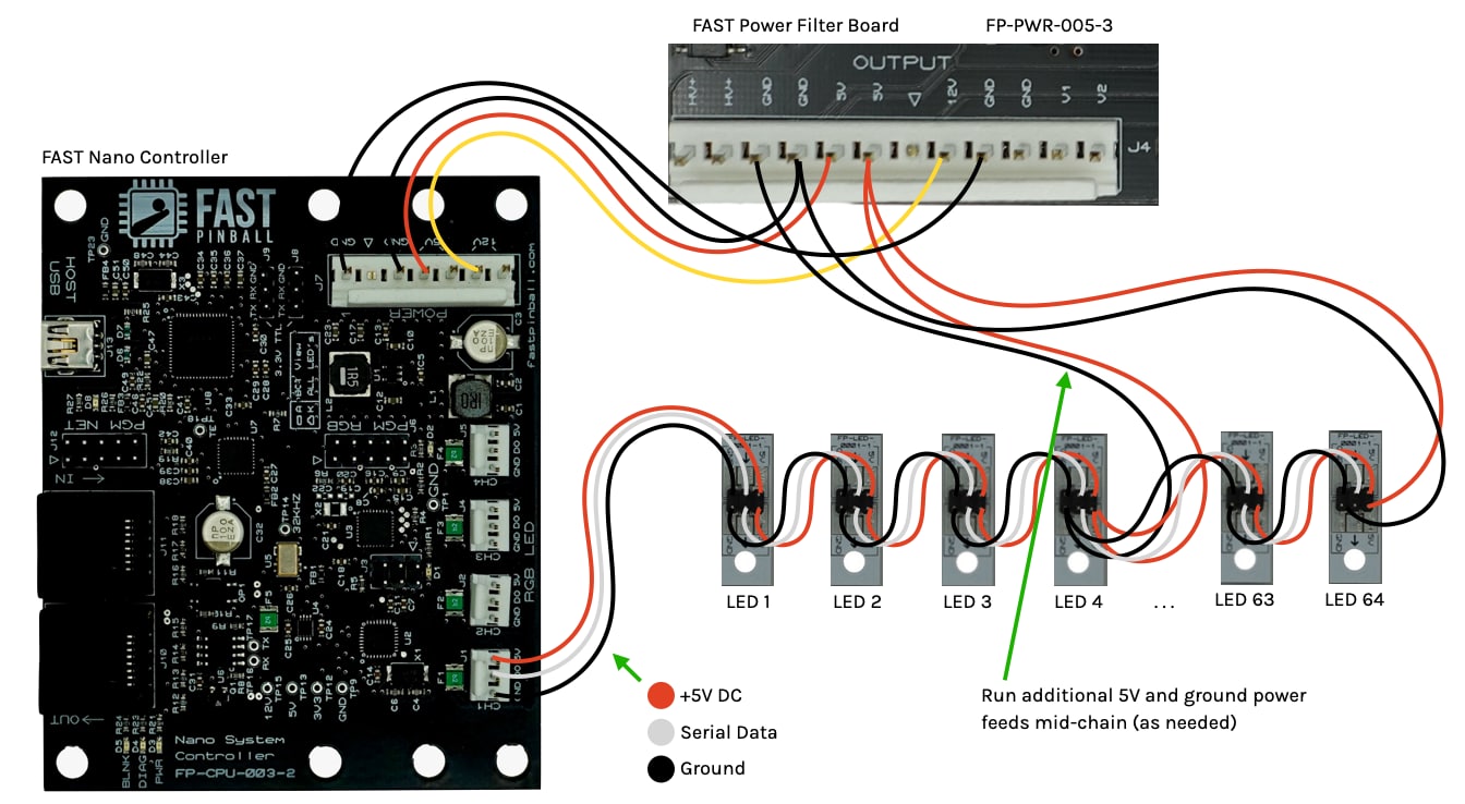
The easiest way to do this is to run another set of power feeds into the end of the chain as mentioned above. But depending on your use case, you might need additional power feeds into the middle of your chain, like this:
The good news is it's really easy to add more, so start with the power from the FAST board itself, and if LEDs at the end of the chain aren't the right color, add a power feed into the end, and then if LEDs in the middle of the chain aren't the right color, add a power feed into the middle.
If you're looking for a hard-and-fast "rule" for how many power taps you need per X number of LEDs, we can't give you that since it depends on so many things, such as:
- More resistance leads to more voltage drop. How much total resistance you have depends on whether you're using connectors or direct soldering wires. And your wire gauge. And how good your connector crimps are. And whether you bought quality connectors or cheap ones. And how much resistance is in your LEDs. (Are they name brand or knockoffs or counterfeit or do you even know???)
- More heat equals more resistance. How warm is the air in your machine?
- More current means a higher voltage drop over a given resistance. How bright are you running your LEDs and how much current do they consume at your brightness levels?
- Different wire brands have different resistance per foot. Do you know yours?
- Different LEDs tolerate different voltage levels.
- Your incoming voltage will dictate how much headroom for a drop there is. At the connector going into your LED chain, what's your "5V" voltage? 5.2? 5.0? 4.8?
All that said, in the homebrew community, it seems like additional power taps every 15-20 LEDs is probably what most people do. Some are 5-10. Really just build your chain and experiment a bit.
Other advice here is to avoid long chains if you can. If you have 80 LEDs in your entire machine, you could run four chains of 20 instead of two chains of 40, etc.
Here are some general guidelines for when you run additional power taps:
- Any time you run an additional 5V power to an LED chain, also connect a ground wire (of the same gauge and wire type) at that same point.
- The "source" of your additional 5V power will be from the 5V and ground terminal distribution points in your machine or directly from the filter board output. (e.g. the same source that provides the 5V power to the Nano which is used for the Nano's end of the 5V LED power.)
- If you have so many LEDs that you need more than 4 or 5A (which, please invite us to play your awesome machine), then you will need to run an additional 5V distribution feed and you'll need a bigger 5V power supply that can support more current. See the guide to getting more power and power distribution for details. (In this case you should treat your 5V LED power as having a toxic ground too.)
As for how you physically connect the power taps into your LED chains, there are a few options:
- You might be able to put 2 wires into each header pin crimp, so you could add them into the connectors themselves.
- You could use wire connectors to tap into the red and black wires in between LED inserts.
- You could solder the power wires directly to the power pads
Dealing with interference
One of the downsides of serial LEDs is that since a high-frequency digital signal is used to control the colors of all the LEDs in the chain, any EMI interference on that wire will cause the LED colors to be weird. The easiest way to avoid this is to not run other wires too close and in parallel with your LED signaling lines. (So if you have your FAST Controller in the backbox, don't put all your LED control lines in the same tightly-packed transmission bundle, and don't bundle up your LED control lines with FAST I/O Loop, switch lines, driver lines, etc.)
That said, you don't have to get too crazy here, just be aware of what's running alongside each other in parallel. This is one of those situations where it might be easiest to just build and wire your machine and then to see if you have any interference once it's done.
Also if you have other wires that need to cross over your LED control lines, try to make the crossover as close to a 90-degree angle as possible.
What if you want single-color LEDs?
The FAST Controllers only directly support serial RGB LEDs. But what if you need to control single-color LEDs? You have a few options.
Use serial LEDs as single color
If you want to have single-color LEDs in your machine, the easiest way to do this is just to use a serial RGB LED and then to only use one color in your game software. If you're putting that LED under a playfield insert that's colored, you can experiment with the best color setting for the LED to make the insert light up in the color you like. For example, somme people like a red LED shining through a red insert, others like to set the LED to white even though it's shining through a red insert. Just play with it and see. But using serial LEDs will be simpler and cheaper than trying to incorporate a traditional non-serial LED.
Also be aware that WS2812-compatible serial LEDs come in all sorts of packages and form factors (including strands of lights almost like Christmas lights and other wild things). You may thing that you need a traditional LED package for some specific location in your machine, but if you search on Amazon or Ali Express you may find a WS2812-compatible version of that which you can wire into your LED chain like any other.
Wiring traditional (non-serial) LEDs
All that said above, sometimes you will need to wire in a traditional, old-school, non-serial single-color LED. There are a few ways to handle this.
First, you could use a driver board output to control that LED just like any other driver. This might be a good choice if you want simpler single-color LEDs for all your GI and you don't care about dimming or anything. In that case you can wire up a whole chain of LEDs and control them with an I/O board driver. (So they'd use 5V instead of 48V, but everything else is the same.)
Another option is to find some WS2812-compatible chip which can be used to drive something else. (All sorts of hacks are available for these types of things.)
This guide is part of our complete series on wiring your FAST Nano-controlled pinball machine. Click to see the rest!
Wiring guides for FAST Nano-controlled pinball machines
We have many guides and a complete wiring walk-through for your entire pinball machine powered by a FAST Nano Controller. Please read and understand all of the wiring guides before you start planning and physically wiring your machine.
Baseline wiring skills & knowledge
Important wiring and electrical background information you need to know before you start planning your machine's wiring.
FAST Nano-controlled Pinball machine wiring guides
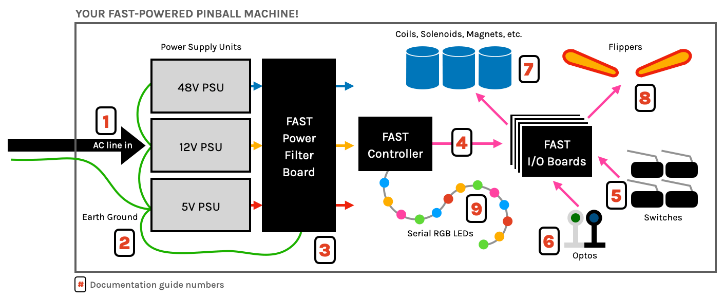
The guides below walk you through a complete machine wiring, section-by-section. The numbers in the drawing match up to the numbers in each diagram. We assume you follow these in order. Click the image to zoom in.
N or > jump the next page, P or < for previous, search with S or ?