FAST Pinball Trough IR Boards
Current Part Numbers: FP-AUX-0001-x (Emitter board) FP-AUX-0002-x (Detector Board)
Previous Part Numbers: FP-AUX-001-x (Emitter board) FP-AUX-002-x (Detector Board)
The FAST Trough IR board set replaces the original Williams boards which connect to a standard Williams trough (6 ball capacity plus "jam" position), letting you use this standard trough in an elegant way with the FAST Modern Platform.
These boards are sold as a set, one is the emitter and one is the receiver. (See our guide to opto wiring for a backgrounder on these technolgies.)
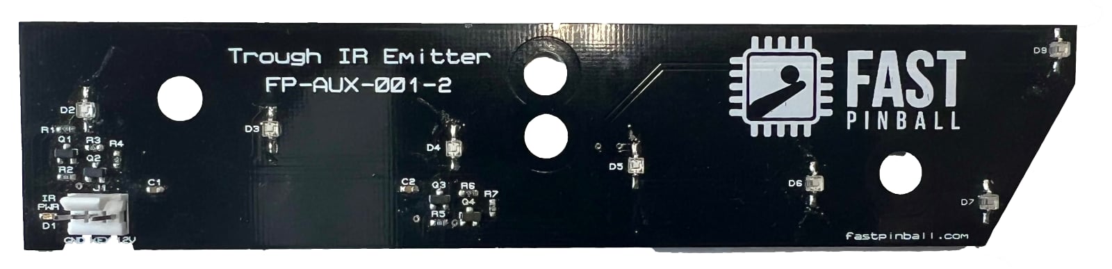
The emitter board takes 12 volts and has IR LEDs which shine through the holes in the trough sides at each ball position.
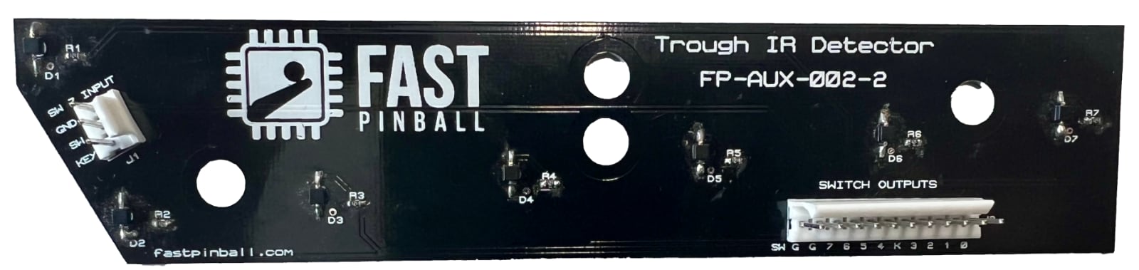
The receiver board plugs into the 11-pin switch header on any FAST I/O Board. The trough itself uses 7 switches (6 ball position switches plus the "jam" position), and there's an additional header you can use to connect the remaining 8th switch position to something, typically a shooter lane switch since it's right there.
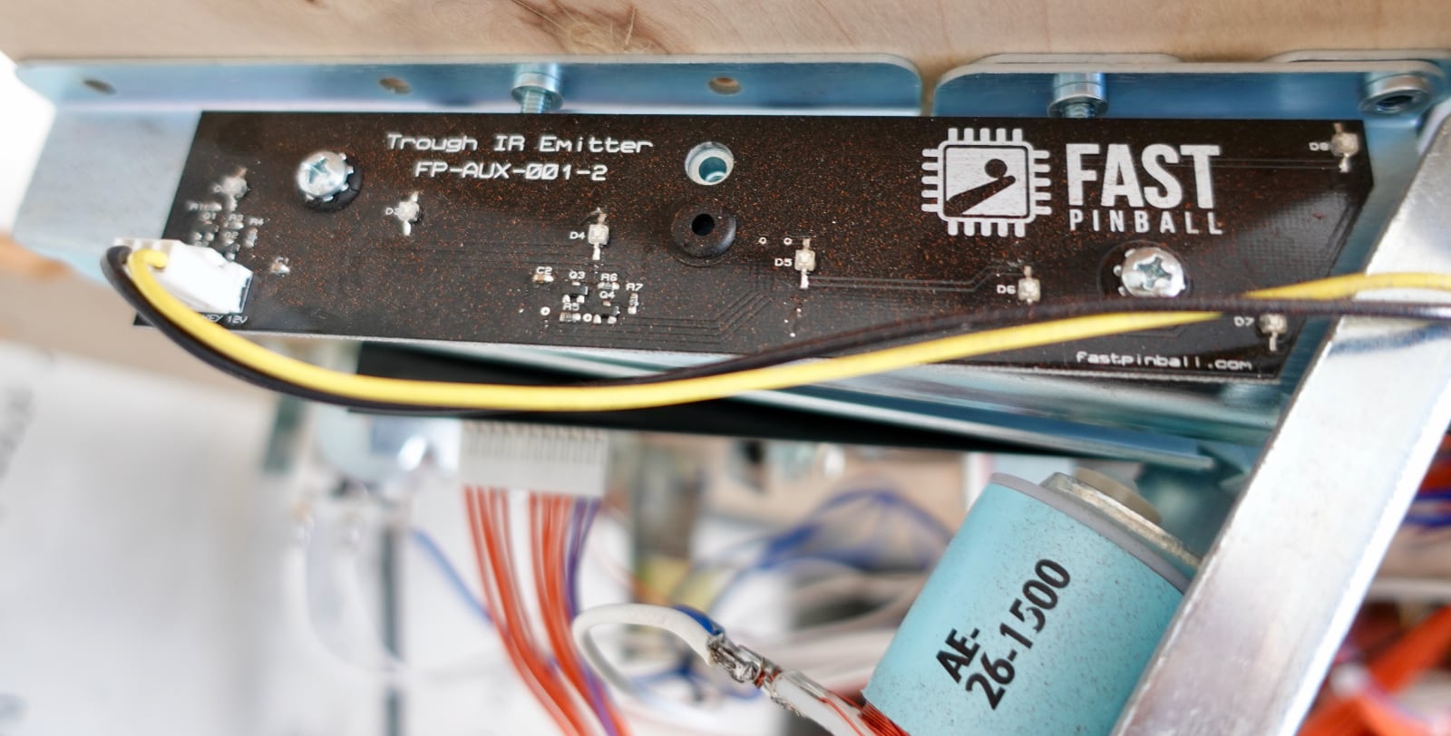
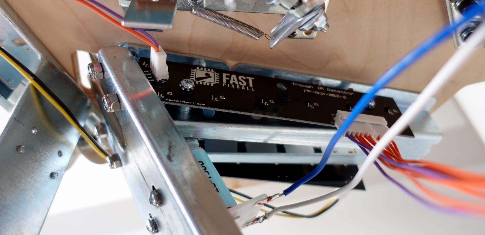
Here are some images showing these boards installed under a playfield.
The emitter side, with 12 volts coming in:
The receiver side. The 11-pin connecter runs back to a FAST I/O Board switch header, and the smaller 2-wire header on the left connects to the shooter lane switch.
Specifications
- The trough IR emitter board has a 3-pin, 0.100" header for incoming 12V. Power consumption is 100mA at 12V.
Features
- Emitter & detector board set modernizes a standard Williams 6-ball trough
- Detector board connects to standard I/O board 11-pin switch header for the 7 trough switches (6 ball positions + jam).
- Detector board has a header to connect an 8th switch, typically used for the plunger lane.
- Emitter board takes standard 12-volt power and has all of the constant current components built-in. No additional IR driver or emitter boards are needed.
- LEDs indicate the balls that are detected, allowing operators to check alignment, dirt, etc. at a glance.
Changes between FP-AUX-001-x and FP-AUX-0001-x
Later versions of this board have a revised switch header which allows the wires to enter the board from along the playfield versus up from the bottom.
FP-AUX-001-x / FP-AUX-002-x are the older versions of the board set with the switch connector facing down.
FP-AUX-0001-x / FP-AUX-0002-x are the newer versions of the board set with the switch connector facing the side.
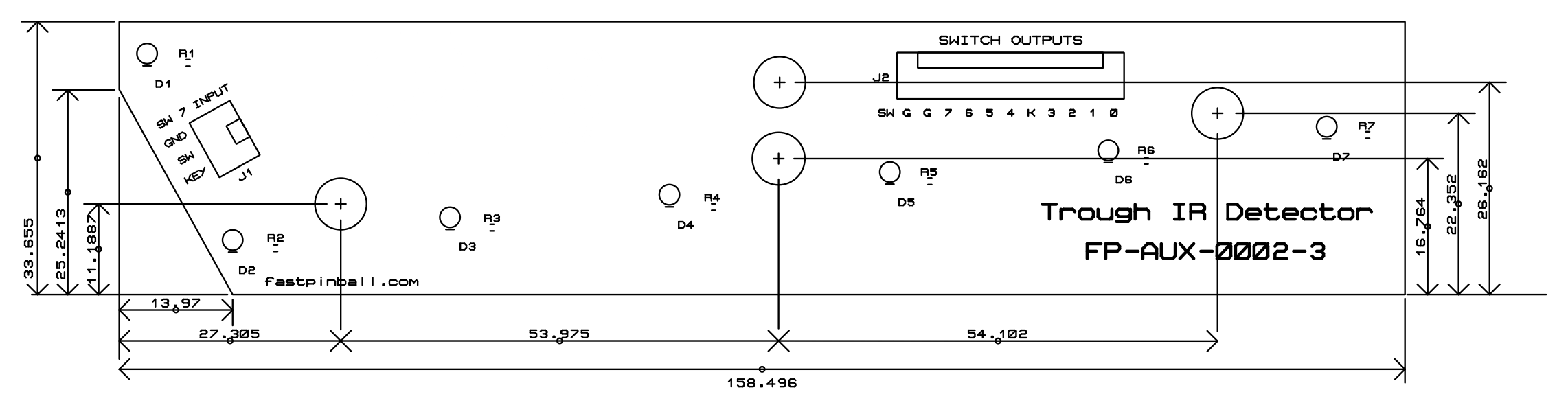
Mechanical Diagram
Dimensions are in mm
Connector Wiring
See the FAST Pinball wiring guide for details on use and wiring.
Wiring Guides
N or > jump the next page, P or < for previous, search with S or ?