How to connect FAST Pinball I/O Boards to a Nano Controller
This tutorial will walk you through the process of attaching and connecting to your FAST Pinball Nano Controller to FAST I/O boards. (Also called "node boards".)
Prerequisites are that are able to use a terminal emulator to connect to the NET processor on your FAST Pinball Nano controller. If you haven't done that yet, check out that tutorial first.
Step 1: Plug in your I/O boards.
First, turn off the power that's supplying your Nano. (The FAST boards can handle being connected live, but it's not a good practice to be fumbling with new hardware near a live running board.)
Connecting your I/O boards is pretty straightforward. You simply connect them all together via the RJ-45 jacks using standard Cat-5 Ethernet cables.
Notice that your Nano Controller and your I/O boards each have two RJ-45 jacks. One is labeled OUT and the other is IN. You simply need to connect the OUT from one board to the IN of the next board. You also need to connect the OUT of the last board in the chain back to the IN on the Nano, completing the loop. That's it! These cables (which create the "FAST I/O Loop") deliver all communication, configuration, and power between individual I/O boards.
It's important to know that even though you're using Cat-5 Ethernet cables, the FAST I/O Loop is not Ethernet. It's not TCP/IP. If you have other random mods or displays in your pinball machine which use the same types of plugs, do not connect them together.
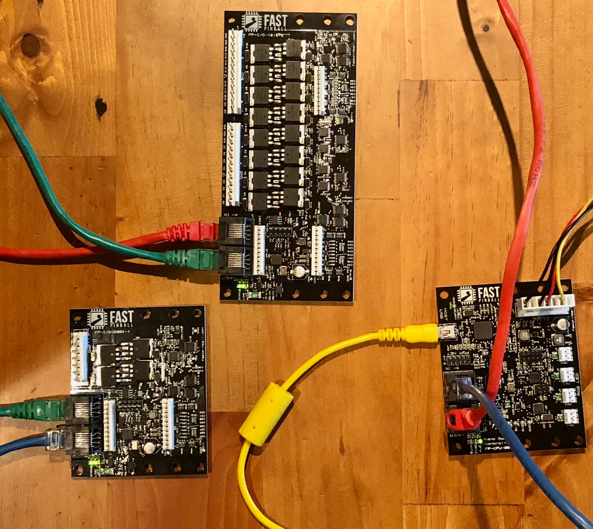
Here's an example I'll use for this tutorial from my own desk. I'm adding a 1616 and 0804 FAST I/O board. The red cable goes from the Nano's OUT to the IN on the 1616. Green goes from the 1616 to the 0804, and blue goes from the final OUT on the 0804 back to the IN on the Nano.
At this point if turn on the power to the supply that's connected to the Nano, you should see LEDs light up on your I/O boards as well (since they're getting power through the FAST I/O Loop)
Step 2. Verify everything via the terminal emulator
Now that the I/O boards are connected and powered up, go back into CoolTerm (or whatever terminal emulator you're using). Connect back to the NET processor (the second of the four serial ports) using the same settings from the previous tutorial. Once you're connected you can send an ID: command again to verify you're connected properly:
id:
ID:NET FP-CPU-002-2 01.00
Assuming that works, try sending a new command CN:. Note that commands are not case sensitive, so you can just type cn: Enter. You should get something like this:
id:
ID:NET FP-CPU-002-2 01.00
cn:

Nodes Configuration:
Node  Name             Ver   SW DR XI XO Node Serial Number
NN:00 FP-I/O-1616-2    01.00 10 10 04 06 D4BEBAB8514C505136202020FF0E0F22
NN:01 FP-I/O-0804-1    01.00 08 04 04 06 3BC7E2D1514C505136202020FF0D0B20
You will have one line for each I/O Board that's attached. The information shown is:
These values are in HEX, not decimal
All configurations and values you see when using a terminal emulator are in hex, not decimal. So the value of 10 in the example above is in hex (usually written like 0x10), which is 16 in decimal.
NodeThe node number of the board. The first board in the FAST I/O Loop is00, the next board is01, etc. The order of the boards is important since that dictates the numbering order of the switches and drivers for each board.NameThe product number for each board. In this case it's showing a 1616 for the first board (Board 0) and 0804 for the second.VerThe firmware version of the processors on each board.SWThe number of switches the board has. (Again this is in hex, so the value of10is 16 in decimal.)DRThe number of drivers each board has (in hex).XIThe number of extended input bytes (deprecated, replaced with FAST Expansion Bus).XOThe number of extended output bytes (deprecated)Node Serial NumberThe serial number of the processor on the board. This can be used to uniquely identify a board which is especially helpful if you have two of the same type of boards in your loop.
Step 3: Hit a switch!
Another very simple and kind of fun thing you can do now is to hit a switch and see the result in the terminal emulator. If you have a real switch with a connector wired onto it, you can plug it in now. Or, just use some jumper wires or test leads or whatever you have that's handy. You can refer to the product docs for the I/O Boards to verify that you're connecting to the proper pins. Just connect one wire to one of the "G" connections on a switch header, and connect another wire (or the other end of your wire) to one of the numbered switch inputs. (0-7 on the 0804, 0-7 or 8-15 on the 1616, and 0-7, 8-15, 16-23, or 24-31 on the 3208)
Here's an example of my setup connected to a 1616, the blue wire is connected to the "G" and the orange wire to the 9.

When you tap the two wires together (assuming the terminal software is still connected), then you'll see something like this:
-N:09
The number 09 in the example above means that this message is for switch number 09. So you will most likely have a different number since you probably picked a different switch. Also these numbers are in hex, so if you see number 0A that's actually decimal switch 10. And if you see 10 that's decimal switch 16, etc.
When you release the wire, you'll see this:
/N:09
Note that the FAST Serial Protocol uses - and / to indicate the current state of a switch. (This is like a little ASCII art version of switch wireform, where / is the up or off position, and - is the down or on position.)
If you just quickly tap the two wires together, you'll see this:
-N:09
/N:09
Pinball machines track the state of every switch, whether it's on or off. So when a switch is activated, one message is sent indicating that, and then when the switch is deactivated, another message is sent. So if you just tap the switch really quick, that's actually two messages really quick--one indicating the switch went active and another saying it went inactive again.
If you connect one wire to the "G" pin, and then take the other end and just run it down the whole row of pins, you'll see something like this:
-N:06
/N:06
-N:05
-N:04
/N:05
/N:04
-N:03
-N:02
/N:03
-N:01
/N:02
-N:00
/N:01
/N:00
Notice that the individual switch on and offs are not in perfect order because I was hitting some together, etc.
Step 4: Understand what's happening
One of the unique aspects of the FAST Pinball Modern Platform is that the individual I/O boards have their own processors on them. This means that all switch processing and debouncing is handled locally by the processor on each board. There are many reasons and advantages for this, including:
- The local processors are able to be extremely fast and precise in their timings.
- Each board's local processor handles switch debouncing, configuring rules, local driver triggering, etc.
- Adding more boards, more drivers, and more switches doesn't slow down or tax the overall system, since each board you add increases the overall capabilities of the entire system.
- Any interference in the FAST I/O Loop doesn't result in "lost" switch events or commands since the processors are in constant communication with each other and know the state of the network and messages.
When the Nano powers up (which then powers up the I/O boards via the FAST I/O Loop), the Nano sends a default configuration down to each connected I/O board. You can change the configuration of individual drivers and switches by sending various configuration commands. For example, if you send a new debounce configuration settings for a switch, that setting is sent down to the I/O board that switch is connected to since that board's local processor is responsible for its configuration.
When a switch changes state, the processor on the I/O board that switch is connected to handles the debouncing, and once that local board has verified the switch change is legitimate, it passes a message along via the FAST I/O Loop which is received by the Nano, and then the Nano forwards the message out via the virtual serial port over USB to the host computer that's connected.
There are other commands you can use to see the configuration of all the switches in the system. For example, try the CS: command which is used to query the state of the switch configurations:
cs:

Switches Configuration:
Switch Output  CL OP
SL:00  True    1E 1E
SL:01  True    1E 1E
SL:02  True    1E 1E
SL:03  True    1E 1E
SL:04  True    1E 1E
SL:05  True    1E 1E
SL:06  True    1E 1E
SL:07  True    1E 1E
SL:08  True    1E 1E
SL:09  True    1E 1E
SL:0A  True    1E 1E
SL:0B  True    1E 1E
SL:0C  True    1E 1E
SL:0D  True    1E 1E
SL:0E  True    1E 1E
SL:0F  True    1E 1E
SL:10  True    1E 1E
SL:11  True    1E 1E
SL:12  True    1E 1E
SL:13  True    1E 1E
SL:14  True    1E 1E
SL:15  True    1E 1E
SL:16  True    1E 1E
SL:17  True    1E 1E
In this example, there are 24 switches (since I have 1616 and 0804 I/O boards). The results here are:
SwitchThe number of the switch, starting with0on the first board and counted up sequently, in hex.OutputShowing whether this switch is configured to report when it changes to the host computer.CLThe debounce time for when the switch closes, in millisecond (hex). The default of1Eis 30ms.OPThe debounce time for when the switch opens.
There's a similar command you can use called CD: which will show you the configured state of the drivers. Connecting drivers is something we'll get to later, since you need to have power and proper wiring and it's not a good test to do on your table top like we've been doing so far. But if you want to see a lot of all the drivers, along with their configurations (which will be default and unconfigured since we haven't sent any configs to them), you can try it like this:
cd:

Drivers Configuration:  WD=FFFFFFFF
Driver Active    Control  SwID  Mode         SW1    SW2    P1 P2 P3 P4 P5
DL:00  Disabled  Auto     00   Unused Driver True   True   00 00 00 00 00
DL:01  Disabled  Auto     00   Unused Driver True   True   00 00 00 00 00
DL:02  Disabled  Auto     00   Unused Driver True   True   00 00 00 00 00
DL:03  Disabled  Auto     00   Unused Driver True   True   00 00 00 00 00
DL:04  Disabled  Auto     00   Unused Driver True   True   00 00 00 00 00
DL:05  Disabled  Auto     00   Unused Driver True   True   00 00 00 00 00
DL:06  Disabled  Auto     00   Unused Driver True   True   00 00 00 00 00
DL:07  Disabled  Auto     00   Unused Driver True   True   00 00 00 00 00
DL:08  Disabled  Auto     00   Unused Driver True   True   00 00 00 00 00
DL:09  Disabled  Auto     00   Unused Driver True   True   00 00 00 00 00
DL:0A  Disabled  Auto     00   Unused Driver True   True   00 00 00 00 00
DL:0B  Disabled  Auto     00   Unused Driver True   True   00 00 00 00 00
DL:0C  Disabled  Auto     00   Unused Driver True   True   00 00 00 00 00
DL:0D  Disabled  Auto     00   Unused Driver True   True   00 00 00 00 00
DL:0E  Disabled  Auto     00   Unused Driver True   True   00 00 00 00 00
DL:0F  Disabled  Auto     00   Unused Driver True   True   00 00 00 00 00
DL:10  Disabled  Auto     00   Unused Driver True   True   00 00 00 00 00
DL:11  Disabled  Auto     00   Unused Driver True   True   00 00 00 00 00
DL:12  Disabled  Auto     00   Unused Driver True   True   00 00 00 00 00
DL:13  Disabled  Auto     00   Unused Driver True   True   00 00 00 00 00
(Driver configuration is pretty wild, check the FAST Serial Protocol reference if you're really dorkily interested.)
Any configuring commands you send to the Nano or the I/O boards are temporary. They are lost when the Nano loses power or reboots.
In an actual pinball machine, the game software (like MPF or whatever you're using) holds all the configurations for the FAST Pinball drivers and switches, and it sends those configurations to the board each time it boots up. (Actually the configurations are constantly changed, updated, and overwritten throughout the course of a game.)
It can be difficult to imagine as we're sitting here now manually playing with an interactive terminal emulator, but the thing to remember is that computers and this serial connection are really fast! The baud rate of 921600 that we configured means that wire passes 921,600 bits per second, and with the terminal settings we're using, each character uses 10 bits. So when the computer is talking to the FAST controller instead of a human, they're moving more than 92,000 characters per second. (All the characters in that driver configuration grid above would be transmitted in 1.7ms, less than 1/500th of a second!)
Troubleshooting
If you can't connect to your Nano, go back to that tutorial and read the troubleshooting there. If you can connect to your Nano but you don't see the node boards:
- Do you see a green light on each board?
- Do you have all the Cat-5 cables connected, including the final one to go back to the Nano?
- Did you confirm the
OUTfrom one is going to theINon the next one? - Are your Cat-5 cables connected directly to each board? No splitters, hubs, etc. (Remember this is not Ethernet!)
What if I see nonsense characters?
It's possible that at some point, you'll see nonsense or weird characters in the terminal emulator. This can happen if you power cycle the Nano while the terminal software is connected, for example, since random electrical impulses could still be on the line as it's fading off or on. If this happens, that's fine, you can always just enter a new id: command, or just hit the enter key and verify you get the expected XX:F response. Here's an example where I just hit Enter three times:
<.<..¿.¸¿¸¿.¿.¿<.<¿.<¿.<..¿.¸¿¸¿.¿¿¿¿<.
XX:F

XX:F

XX:F
Next steps
At this point, if you can send an ID: and CN: can get information on your controller and I/O boards, you're ready to start building some pinball! If you're using the Mission Pinball Framework, you now have all the information you need to follow their tutorial and get your boards connected and talking to MPF.
If you're going to write your own software from scratch, you're ready to start exploring.
These two commands we used, ID: and CN:, are just two of the many commands that are part of the FAST Serial Protocol. If you'd like to explore more, you can look at the FAST Serial Protocol reference on this site. We have lists of all the commands as well as the data they return and how to use them.
Again, if you're just using FAST Pinball hardware to build a pinball machine, you probably do not care about this. You will rarely (if ever) connect to your FAST controller via a serial terminal. You will just use the Mission Pinball Framework or whatever other high-level framework you choose. The FAST Serial Protocol command reference are for people who aren't using MPF and/or who want to write their own code from scratch or who want to create their own high-level framework.
N or > jump the next page, P or < for previous, search with S or ?