Understanding ground lines and grounding in a pinball machine
Or, why do my LEDs blow out and my boards reset when a lot is happening at once?
Wiring, high voltage, and electricity can be dangerous. Read this first!
The voltages and electricity discussed here can be dangerous and could cause property loss or death. It is your responsibility to ensure you are aware of these risks and comfortable with these processes. Furthermore your local jurisdiction may have regulations or rules which differ from what we discuss here, including wiring colors, standards, techniques, etc. Although based on broadly adopted methods, FAST Pinball does not employ Professional Engineers and this information is not professional recommendations. There may be errors, omissions, or typos here. Any pinball machine available to the general public should be reviewed by a licensed Professional Engineer in your region. Use this content at your own risk.
In the electrical engineering world, the place where you measure zero volts (0V) is called "ground". This sounds simple, though if it were truly that simple we wouldn't have all these different types of ground: return ground, analog ground, digital ground, earth ground, protective ground, chassis ground, and (our favorite term which we created to describe the ground that controls coils) "toxic ground". Are all these grounds really all 0V, and what happens if/when they get mixed up or combined?
In a perfect world where wire conducted all the electrons that wanted to flow through it, there would only be one term for ground: "regular ground." :) In that perfect world we wouldn't need calculators to figure out what's really happening, and Ohm's law wouldn't be a thing. Even if you don't want to be an electrical engineer and just want to build pinball, you still need to know that Ohm's law exists, because by the time you're done building your machine, you will absolutely know all about it.
The details of Ohm's law aren't important for now. (Click the Wikipedia link above for details.) The important takeaway for now is that (1) Ohm's law is the most-used formula in electrical engineering, and (2) it describes the relationship between voltage (volts), resistance (ohms), and current (amps), and how changing one affects the others.
In the real world, wire has resistance. This means that from an electrical engineering standpoint, what you think of as a "wire" is in reality a "really long and bendy resistor". Sure, the resistance of wire isn't too high. (For example, the 18 gauge wire we use for most coils in a pinball machine today has a resistance of 6.385 ohms per 1,000 feet.) But if you take the resistance in the wire (remembering to double the resistance of one wire since you need to consider the complete circuit when calculating resistance) and add in all the resistance of the various crimps, connectors, solder-joints, boards, internal resistance in the power supplies, etc., you'll find that the total resistance in any pinball circuit is non-trivial.
The problem
So, wires are resistors. Who cares? The reason we care is that coils in a pinball machine require a lot of current to create their powerful mechanical motion. Ohm's law shows that high current moving through resistance (the wire & connectors) will cause a voltage drop. This voltage drop is something we need to plan and design for when we're wiring our pinball machines.
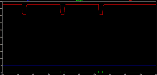
Let's walk through an example to illustrate this. The graph below shows voltage over time. The blue line is the 48V powering a coil, and the green line is its return ground. Since ground is 0V (in theory), it's zero when the coil is not on. But when the coil turns on, you see that 48V falls. This makes sense, again, since Ohm's law shows that high current moving through resistance (the wire, etc.) causes voltage to decrease. In this case, when the coil is activated, the 48V drops to about 40.6V.
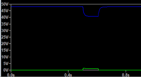
Makes sense so far, right? The potentially unexpected part is the green line showing the ground return of the coil circuit. That line was 0V when the coil was off, but when the coil was activated, the voltage on that ground return line INCREASED from 0V to about 1.4V! What?? The reason for that increase is because the circuit is a complete loop. In theory the +V decrease and the ground increase should be the same, though the real world is not perfect due to different wire lengths, connection paths, etc.
"Voltage" is simply a measurement of the difference in potential between two points. So if your +V drops to 40.6V, and your ground rises to 1.4V, that means the actual voltage across those two points is 40.6 - 1.4 = 39.2V. This is still enough for the coil to work (and you'll see in further guides that the FAST Power Filter Board has some large capacitors which kick in to boost the voltage back up during this voltage drop.)
So this power circuit for the coil is fine and operating as expected if it were isolated.
But what would happen if this 48V power circuit for your coils was sharing the same ground as the 5V power circuit used to power your boards and LEDs?
In that case, when the coil fired and the ground rose from 0V to 1.4V, that would mean the 5V supply would see its ground rise to 1.4V too. This has the effect of only leaving 5 - 1.4 = 3.6V for your 5V power line! This is what leads to things like brownouts, weird LED colors, and processor resets.
And that's not even the worst part! Because the coil is an inductive load (meaning it stores energy in the form of a magnetic field), when the coil turns off, that magnetic field releases its energy back into the wires in the opposite way it came in, meaning those voltage changes are reversed! The 48V will go above 48 and the ground will go below zero. So now if your 5V line is sharing the same ground as the 48V, if the ground drops to -1.4V then you have 5 - (-1.4) = 6.4V on the 5V line which could blow out LEDs or damage other 5V components. (And that's just with a single coil. What would happen if you have 2-3 firing at once and everything's sharing a ground line? This is why homebrew machines built by people who don't understand what they're doing keep breaking.)
Sidebar: This coil collapse current is why we put flyback diodes across the coil lugs. While those prevent that over voltage from getting back to the I/O boards, they don't prevent ground reference fluctuation.
The solution? Separate ground wires
Luckily there's a simple solution to this, and that's to run separate ground wires. This is why at FAST Pinball we refer to the 48V ground as the "toxic ground" and the low voltage ground as "clean ground". While they both have "ground" in their names (since they both ultimately connect back to the ground tie point), they are not the same lines and they are not interchangeable.
By the way, in the FAST Modern Pinball platform, the toxic ground and clean grounds are connected to each other via the internals of the Smart Power Filter Board. Within that board, those two grounds have a fat connection to each other with almost no resistance, and connecting them in that board instead of out in your machine means that the ground fluctuation of the toxic ground will not affect your clean ground in the machine.
Why was this not a problem in the past?
So now you know what you need to know for your modern machine. But for some more trivia on this topic, it's interesting that in older pinball machines, up through the 90s or 2000s, running all these separate ground lines wasn't a problem because the power transistors that drove the coils were all on that big driver board in the backbox, and the backbox had the lowest ground potential in the entire machine since all the power was combined back there. (Not to mention there was a huge chunk of metal behind all the boards which was a super low resistance ground plane!) It was pretty much the most ideal situation you can have. Good thinking pinball forbearers!
If we were trying to perfectly emulate that old environment using the modern FAST Pinball platform where the driver transistors are near the coils, then we'd need to run individual ground lines from every coil back to our 0V ground reference point. Of course that's not practical, so instead we designed the FAST I/O boards with protections to make them less sensitive to voltage fluctuations, meaning you don’t need the half-mile of wire needed in the older games.
I/O board grounding
Actually while we're on this topic, now's a great time to explain how this works in the modern FAST Pinball world. Each FAST I/O board has two sets of grounds: a toxic ground and a clean logic ground. (The clean logic ground connection is provided by the FAST I/O Loop via the Cat-5 cable loop.) Individual I/O boards are designed to float their grounds higher and lower as needed based on the specific coils that are firing and collapsing at any moment that are attached to them. (You can almost visualize all the IO Boards floating on top of a choppy ocean of locally-variable ground references.)
This is why it's very important that your switch returns go back to the same board as the switch inputs. (e.g. Both wires of a single switch must always be connected to the same I/O board.) If you connect a switch input to one I/O board and its ground to another, then it's possible that the two I/O boards that single switch is connected to have different local ground references at any given moment. And if that's the same moment in the game when that switch is set, now that switch becomes a local ground tie point for an instant which could in theory cause you to have the hat trick of over-voltage, under-voltage, and "hey my switch is a fuse now" situations at the exact same time!
So always connect each switch to just one board, and do not tie your switch returns into your ground.
Digging a little deeper
Dave (FAST Pinball CTO) built a simple simulation a while back at one of the trade shows using LTspice (a free tool if anyone wants to play with this more) to show this phenomenon. The story as he tells it:
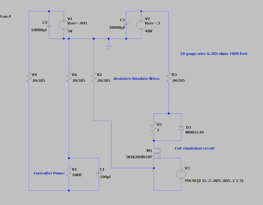
I was trying to find out how a poorly wired machine was actually behaving via a simulated model. R2, R3, R4 and R6 represent the wires going from the power supply filter board to a coil and the FAST Controller. R1 and C1 represent the power going to the controller. The coil for this model is resistive only and represented by R5 and is being controlled by M1 (a high-power MOSFET). This is an example of a well wired machine. R2 is ground for the high voltage, and R3 is the 48V going to the coil. R4 is the 5V wire going to the FAST Controller, R6 is the ground wire going to the fast controller.
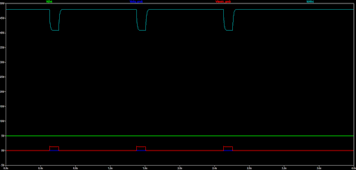
Below is the simulation of a well-grounded machine where the waveforms look great! The upper light blue line is the 48V supply, and the red line is the ground for the 48V supply. When the coil is turned on, we see 48V go lower and 48V ground line rise. The green line (5V) does not move, and the blue line (which you can see between the red line) 5V ground does not move as well.
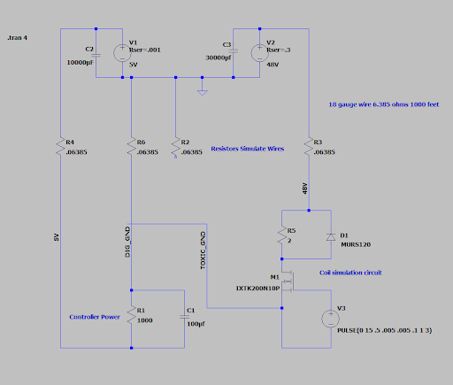
Ok, now let's look at poorly wired machine. In the below schematic we are now sharing a ground between the 48V and 5V supply. R6 represents the wire being shared that goes between the filter board /power supplies to the FAST controller ground and the coil ground. The ground wire represented by R2 is no longer in the circuit. Everything else in the circuit matches the example in the previous simulation.
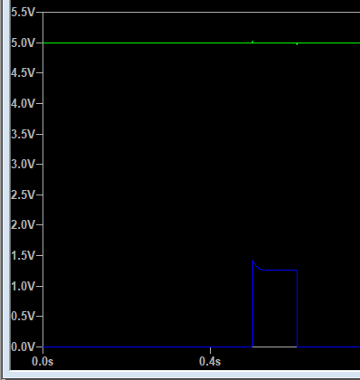
Now since there's only one ground (green line), we see the 5V supply is no longer getting 5V when the coil is fired. You have to measure from 5V (blue line) to the green line to see what voltage the controller would be actually getting.
Zoomed in view of just 5V and GND. 5V is now around 3.5V (in reference to ground)
In Summary: Run several grounds for separate loads and combine them close to the source (power supplies/filter board). You should have very few problems if that rule is followed. It's better that there are too many than too few grounds. Be sure to label them appropriately if you ever create a wiring diagram for your machine. (Toxic, Logic, LED, etc.)
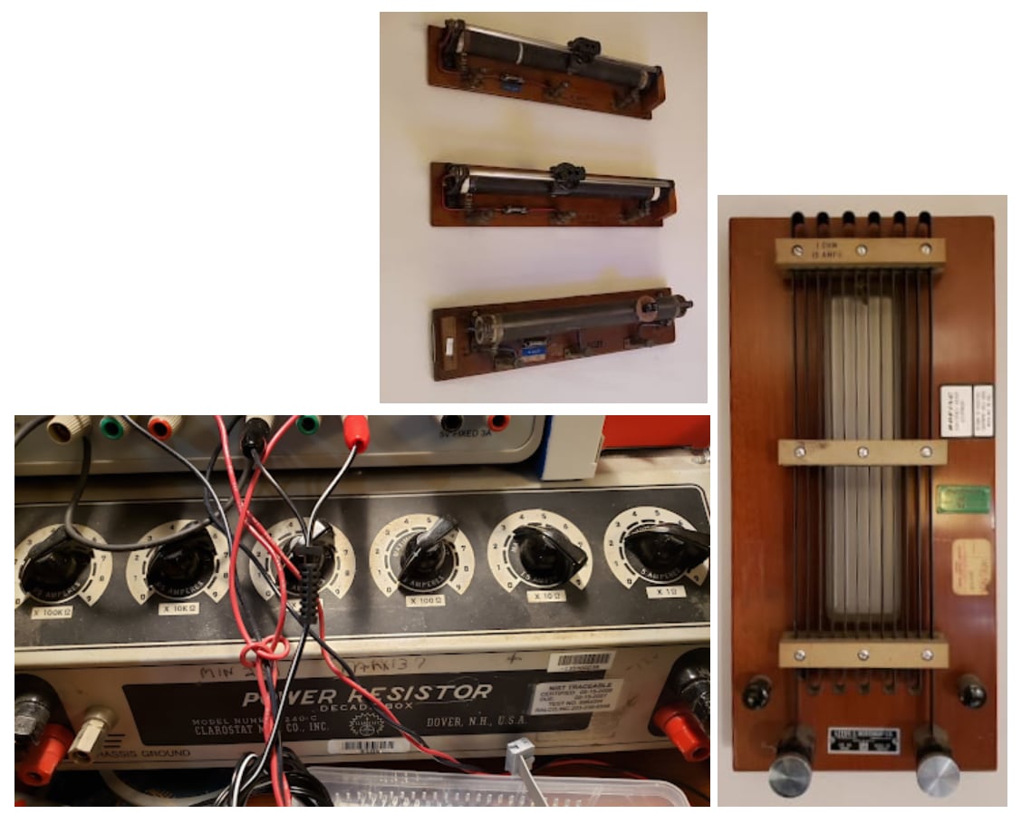
Finally, here's a look at some old school tools used in the creation of the FAST hardware. These were used for loading and observing currents during active coil firing. We use some newer active loads as well, but I love the workmanship of the classic stuff.
N or > jump the next page, P or < for previous, search with S or ?