Cabinet wiring layout & power distribution in a FAST Nano-controlled pinball machine
Wiring, high voltage, and electricity can be dangerous. Read this first!
The voltages and electricity discussed here can be dangerous and could cause property loss or death. It is your responsibility to ensure you are aware of these risks and comfortable with these processes. Furthermore your local jurisdiction may have regulations or rules which differ from what we discuss here, including wiring colors, standards, techniques, etc. Although based on broadly adopted methods, FAST Pinball does not employ Professional Engineers and this information is not professional recommendations. There may be errors, omissions, or typos here. Any pinball machine available to the general public should be reviewed by a licensed Professional Engineer in your region. Use this content at your own risk.
This guide is old (for FAST Nano-powered machines only)
This wiring guide is for pinball machines powered by a FAST Nano Controller. If you have a FAST Neuron Controller, please see the Neuron wiring guide.
In this guide, we're going to look at strategies for cabinet wiring, including power distribution block and transmission wiring.
Build a power box
We have several guides on the power side of your machine's wiring, including AC line in & power supply wiring, earth ground wiring, and power filter board wiring. Those guides provide all the detail you need to know how to wire your power.
There's one more thing we want to add to them, and that's the suggestion that you build a single "box" to contain all high voltage and power supply components. Take a look at the diagram which shows this. (Click to zoom)
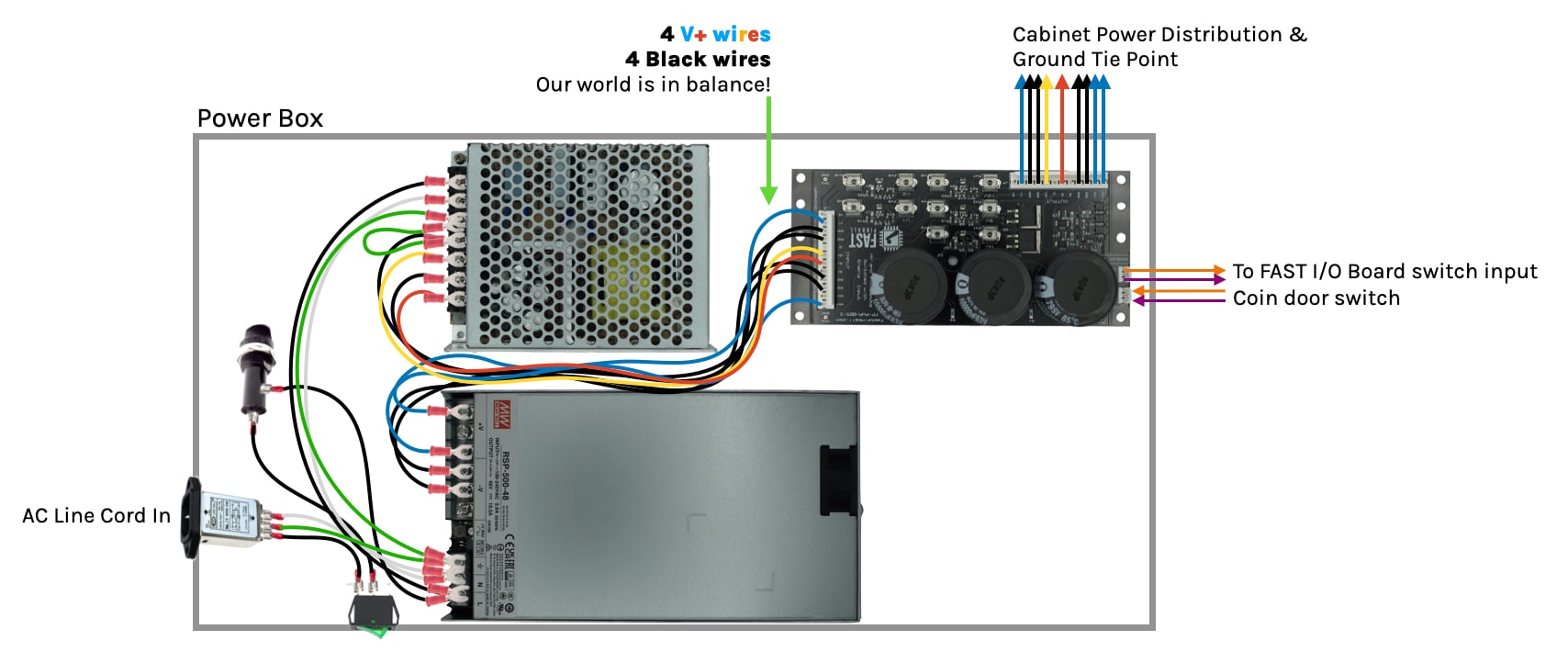
This power box includes the AC line in, main power switch, main line fuse, your power supplies, and the FAST power filter board.
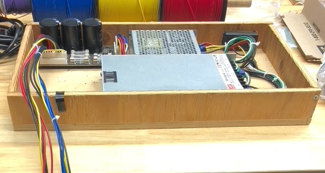
Here's a photo of an actual power box we built in real life. Building this can be a great step early on in your machine build process since this box is self-contained and has everything you need to power your FAST boards and other components on your workbench, and then when you're ready to move to your real machine you can just drop the power box in as-is. (The only suggestion we'd make is to ensure your side walls are tall enough so you can put a metal or plastic over on top of it. That's something we didn't do with the box below.)
Also make sure you allow for airflow or cooling for your power supplies and any fans.
If you build a box for bench testing, remember to jumper the ENA switch closed in order to enable the high voltage taps.
Power box location
Even if you don't build a standalone power box, we suggest you install all the pieces of the power box into a single part of your machine which lets you isolate them by building a wooden, plastic, or metal enclosure and/or cover. (Really you just need to make sure that no one can touch the high voltage, and that nothing can fall onto the power supplies and short them out. Also if you end up with a metal cover or enclosure, be sure it's connected to earth ground!)
The two potential locations for the power box are in the back box or in the cabinet.
Putting the power box in the backbox is nice because then you don't have any high voltage or AC in the cabinet itself. The downside is that your power switch is also going to be in the backbox which can be difficult to reach when your machine is packed in a row with others.
Putting the power box in the cabinet means you can run the main power switch into the traditional right-front area of the cabinet, though that means you have AC running through your cabinet which you need to protect.
Our suggestion is to keep the power box in the backbox so you don't have to worry about AC and high voltage in the cabinet.
Power distribution blocks
Once you build your power box, you'll end up with at least four different power feeds coming out of it:
- 48V
- 12V
- 5V
- Ground
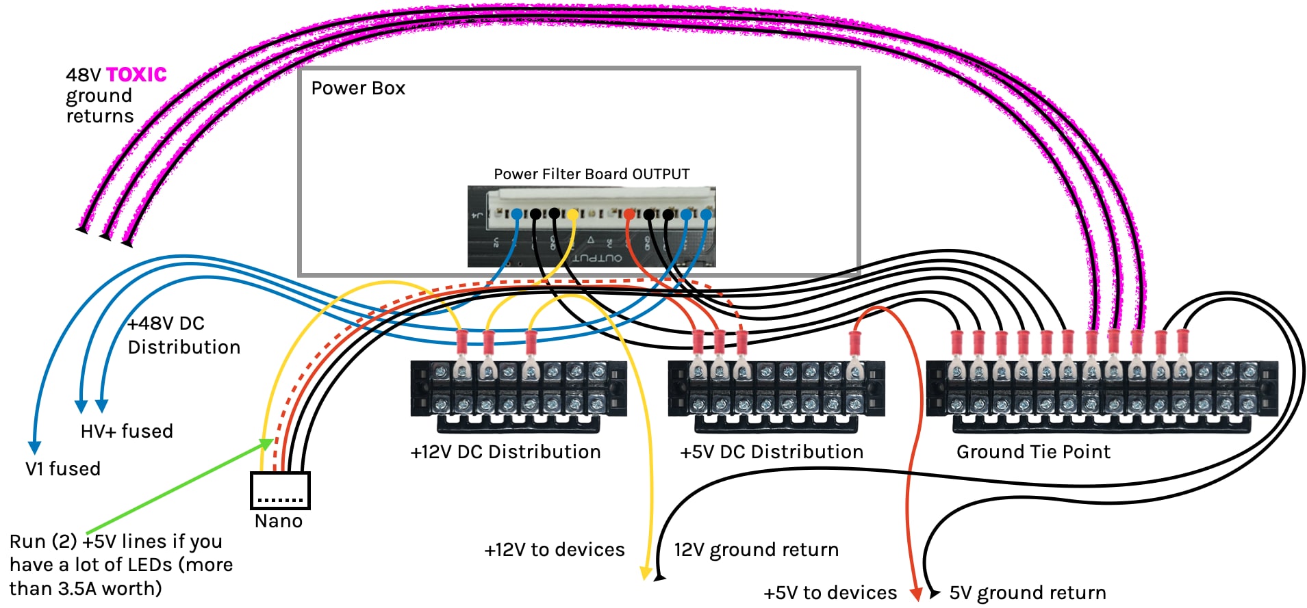
Since you'll need this power at many locations throughout your machine, you'll probably need more than just one or two wires of each. The easiest way to distribute the power throughout your machine is to connect the power lines coming out of the power box to screw terminal strips, like this:
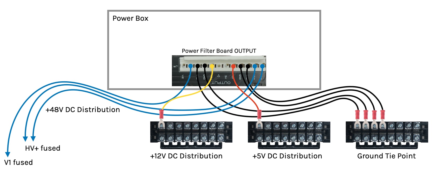
Note that the +48V DC does not have a terminal block. There are a few reasons for this.
First, remember that the HV+ filter board output is a separate load (with a separate fuse) from the V1 line. So you would not want to combine both of those on the same terminal block since then they would be sharing two fuses which can lead to unexpected behavior, and they are each enabled by their own MOSFETs and you don't want positive voltage pushing back on the other side of the MOSFET while voltage levels are changing with the high-current coil firings. You need to keep them separate.
Remember from the guide to coil wiring that the +48V DC blue wire just goes from coil to coil to coil. (Or magnet, motor, whatever.) And since there aren't that many coils in your machine (compared to switches and LEDs), and since you need to run separate lines anyway (for the voltage drop compensation), in many cases it's easier just to run a single daisy-chained wire to each coil.
Of course if you have the room and you prefer terminal blocks, go for it! (You could even get smaller 4-6 position blocks.) Just make sure you don't interconnect between the different fused load lines.
Distributing multiple lines of the same voltage
The power distribution terminal strips are used for convenience. They don't increase the overall amount of power that's available since the terminals are fed by the limits of whatever wires are coming out of the power box to them. Even though an 18 gauge wire can safely support 6A (for example), adding three wires to a terminal block isn't going to give you 18A if that terminal block is getting its power from a single wire protected by a 6A fuse on the filter board.
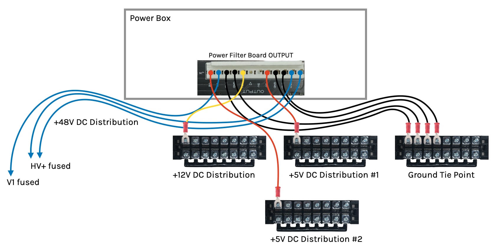
In our guide to adding power, we showed how you could add a 2nd distribution line for your 5V power supply, allowing you to get 12A of 5V power in scenarios where you have a lot of LEDs. Remember that each of those are protected by their own fuse—the 5V and V2 lines on the filter board. This means you will need a separate +5V distribution block for each one. (Of course you don't have to use distribution blocks. You could wire up the 5V and ground directly to your strands of LEDs.)
Adding additional distribution blocks is easy. This diagram shows two 5V distribution blocks. Notice they are the +5V only, the 5V ground returns will go back to your ground tie point (which will probably have more terminals than this drawing is showing, though again keep in mind that you can attach multiple connectors to a single screw terminal.)
People ask if it's ok to let those two different 5V supply lines connect anywhere in your machine. For example, what if the Nano receives its 5V from +5V Distribution #1, and then you plug an additional power feed into the end of an LED chain from +5V Distribution #2. Now you have part of the chain protected by #1's fuse and part by #2's? What???
This scenario is acceptable as long as those two 5V feeds ultimately go back to the same power supply. If you kept the original 6A 5V PSU and then added a second 5V PSU with its own feed, then you cannot connect your two 5V taps in this way. But if they go back to the same PSU, this is fine.
In this scenario, (two 5V feeds with their own fuses going back to the same PSU), you also still get appropriate fuse protection. Let's say each 5V feed was protected with a 5A fuse (via the 5V and V2 lines on the filter board). If you have one feed going to the Nano and the other feed boosting a long LED chain, if either feed breaks (loose wire, blown fuse, etc.), that will shunt more load onto the remaining 5V feed, and if it then becomes overloaded, its fuse will blow too. (Again which is what we want!) So this is fine. (We still prefer to keep the two feeds separate in terms of distribution, but if they ultimately connect, that's fine.)
Ground tie point
We talked about the machine's ground tie point in our guide to pinball ground and grounding. The most important thing about your main ground tie point is that it is physically close to the power filter board and power supplies. Because you will ultimately tie all the DC grounds together in your machine, you will end up with a lot of wires to connect. (Remember again that some connectors support multiple wires, and you can insert multiple connectors into the same screw terminal, techniques you'll most likely use for your ground terminal.)
You also might end up with multiple ground terminal strips. This is fine, as long as you keep a few things in mind:
- Connections between ground terminal strips should be with multiple wires. Consider your overall system design and loads, but it could easily be 2-3 wires connecting blocks together.
- Remember the TOXIC ground from the driver headers on the I/O should be isolated from all other grounds until it gets to the main ground tie point near the filter board. See the driver wiring guide for details.
- If you install ground headers under your playfield, isolate the TOXIC coil grounds from the others. If you have lots of LEDs and 5V LED grounds, treat them as another set of toxic grounds and isolate them all the way to the main ground tie point.
- The 2-3 toxic grounds from each I/O board can all go to a single ground terminal strip under the playfield. Then 3 wires can run back to the main ground tie.
Make your wires long enough!
While we're talking about cabinet wiring, one tip that MULTIPLE homebrew pinball makers shared with us is to make sure your wires and wiring harnesses are long enough to account for the slack needed when you transfer your playfield into a final cabinet.
From the playfield, this will include maintaining enough slack to pull the playfield forward and then tilt it back against the backbox for maintenance. For the backbox, ensure you wiring is long enough to allow the backbox to fold down. Remember it's not a flip-down hinge, it's on a long lever. That backbox moves more than one foot forward when it's folded down, and your wires will need to be long enough to account for that!
Transmission bundles
As we've mentioned in other wiring guides, there are different specifications for wires when they are used for "transmission" versus "branch" circuits. A transmission bundle is when you have a bunch of wires bound together, like with zip ties, string, mesh sleeves, etc. Branch wiring is when individual wires are going to their actual end points and are sort of in the air by themselves.
In classic 1990s pinball machines, there were lots of transmission bundles since all the boards were in the back of the machine and all the action was on the playfield. But in modern day FAST Pinball machines, the I/O boards are distributed and located under the playfield, meaning there's a lot less wire in general to deal with.
The key with your long transmission bundles is not to bundle in wires with high-frequencies, which could include:
- AC power lines
- Serial LED lines (all of them, including power, since Ohm's law can make the power lines into EMI transmitters too)
- FAST I/O Loop Cat-5 cables
- Servo or stepper control lines
Luckily these types of wires will end up being the minority in your machine. Your long runs will probably be power, grounds, and driver control lines, all which you can safely bundle together.
Switch lines won't be as long since they are "local" to their nearest I/O board. (And remember, again, to return both wires from every switch back to the same I/O board.) LED lines and the FAST I/O Loop are their own things, and servos and stepper control lines will also be short. So really wiring up your transmission bundles should be pretty straightforward.
Cabinet, Backbox, and Playfield interconnects
One final thing to consider before you start wiring your machine is whether you want to make it easy to completely separate the cabinet, the backbox, and/or the playfield. We are not necessarily suggesting that you make this easy, rather, we're suggesting that you think about it before you start you wiring so if you want to do this then you plan for it.
The easiest way to plan this out is to think about what pieces will live where. For example (and of course your machine might be different):
Backbox
- Power Box (AC input, PSUs, FAST Power Filter Board)
- AC in
- +48V, +12V, +5V, Ground out
- Earth ground braid
- FAST audio interface
- FAST controller
- Host computer
- LEDs
- Main Display
- Earth ground braid
- Speakers
- Knocker (this could also go in the cabinet)
- Topper
Playfield
- I/O Boards for all coils & switches
- +48V
- Toxic grounds
- FAST I/O Loop Cat-5 cables
- 12V playfield devices
- Opto boards
- Trough opto
- Servos / steppers
- More?
- LEDs
- Earth ground braid
- Secondary display (HDMI?)
Cabinet
- Cabinet I/O Board
- Switches
- Flipper buttons (Will you use two-stage switch inputs for upper flipper control) (2-4)
- Start button (1)
- Launch button (1)
- Lockdown bar button (1)
- Coin door interface operator buttons (4)
- Coin / bill acceptor switches (4)
- Plumb bob / slam tilt (2)
- Coin door open interlock switch (1)
- Headphone volume buttons (2)
- Drivers
- Shaker motor
- Knocker (Alt. location since I/O Board is here?)
- Switches
- Bill validator power (12V? 24V? 120V?)
- Headphone jack
- Cabinet lighting
- Subwoofer
- Earth ground braid
Another way to think about this is what's connected to what. Here's a quick run through (assuming your FAST controller is in the backbox.)
Backbox ↔ Cabinet Connections
- LED wiring (Under cabinet lighting? Flipper button lighting? Lockbar button?)
- Subwoofer audio
- Two Cat-5 cables for I/O board for cabinet switches & drivers (shaker motor, knocker)
- Headphone jack
- Earth ground braid
- 5V (LEDs)
- 12V (shaker motor, flipper optos, coin door)
- 48V (knocker)
- DC ground return
- Toxic ground return
- Power for bill validator
Backbox ↔ Playfield Connections
- LEDs
- Two Cat-5 cables for FAST I/O Loop to I/O boards
- +5V (additional LED power taps)
- +48V (coils)
- +12V (optos)
- DC ground return
- LED ground return (if separate from DC ground)
- Toxic ground return
- HDMI (if you have an additional display on the playfield)
Cabinet ↔ Playfield Connections
- Possibly two Cat-5 FAST I/O Loop connections between I/O boards
Obviously this is a generic list, and you might have more or fewer things. (Did we forget anything? Email me via the green doc feedback link at the bottom of the page!) The key is for you to think about what kind of connections will be needed between all three pieces, and whether you want to make it easy to disconnect everything?
For example, you might make an interconnect point on the playfield where the FAST I/O Loop, LEDs, and power plugs in. That way you have one place to unplug everything if you need to remove the playfield. Same for the cabinet. Maybe everything is on connectors or headers, and simply adding a connector in the neck for the sub and headphones might be a simple thing you can do now to help people disassemble the machine in the future.
Again, it's totally fine not to change any plans for these things, we just want to ensure you've thought about them upfront.
This guide is part of our complete series on wiring your FAST Nano-controlled pinball machine. Click to see the rest!
Wiring guides for FAST Nano-controlled pinball machines
We have many guides and a complete wiring walk-through for your entire pinball machine powered by a FAST Nano Controller. Please read and understand all of the wiring guides before you start planning and physically wiring your machine.
Baseline wiring skills & knowledge
Important wiring and electrical background information you need to know before you start planning your machine's wiring.
FAST Nano-controlled Pinball machine wiring guides
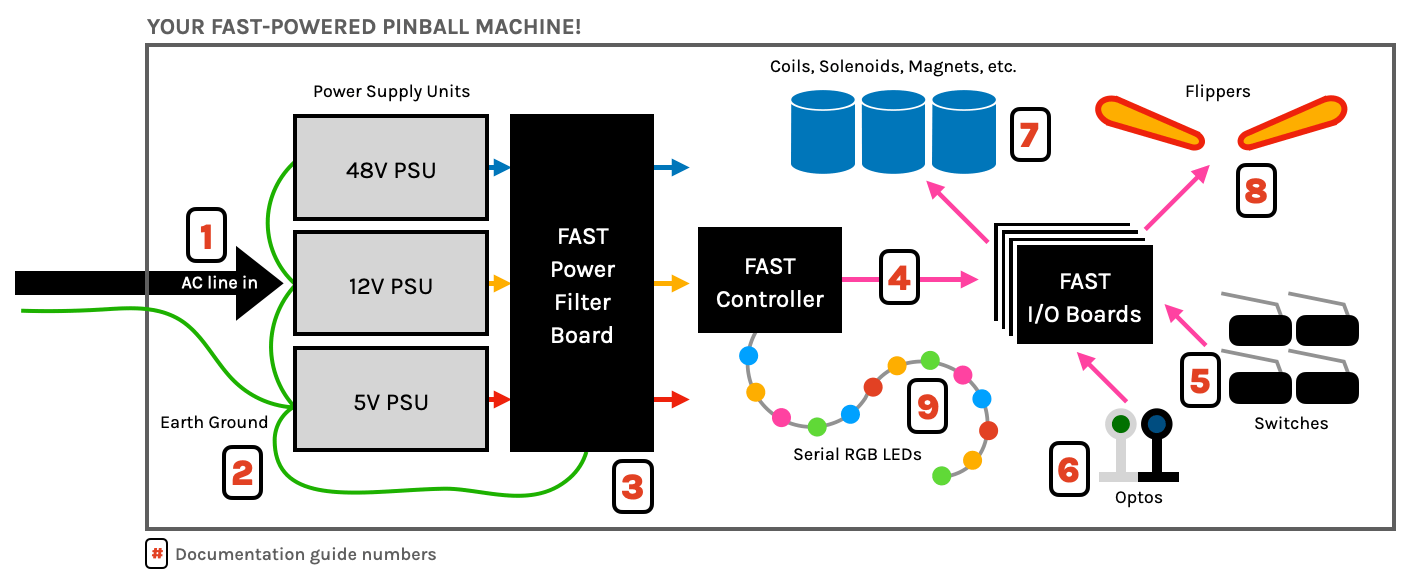
The guides below walk you through a complete machine wiring, section-by-section. The numbers in the drawing match up to the numbers in each diagram. We assume you follow these in order. Click the image to zoom in.
N or > jump the next page, P or < for previous, search with S or ?