How to wire the playfield interchange board in a FAST Neuron-controlled pinball machine
Wiring, high voltage, and electricity can be dangerous. Read this first!
The voltages and electricity discussed here can be dangerous and could cause property loss or death. It is your responsibility to ensure you are aware of these risks and comfortable with these processes. Furthermore your local jurisdiction may have regulations or rules which differ from what we discuss here, including wiring colors, standards, techniques, etc. Although based on broadly adopted methods, FAST Pinball does not employ Professional Engineers and this information is not professional recommendations. There may be errors, omissions, or typos here. Any pinball machine available to the general public should be reviewed by a licensed Professional Engineer in your region. Use this content at your own risk.
The FAST playfield interchange board is a small, mostly passive interconnect board which connects your playfield and the rest of your machine. It sits underneath the back of your playfield and acts as a power distribution point (48V & 12V) for playfield power.
A bonus benefit of the playfield interchange board is that it provides a single connection point for the playfield to the cabinet, meaning you can completely disconnect and remove your playfield from your machine by simply unplugging 1 power connector and 3 network cables from this board at the back of your playfield. This modular approach means you can easily move your playfield from your machine to a rotisserie or bench for service, or even take it to a friend's house to show off your work.
The playfield interchange board is included in the FAST Neuron Starter bundle and is recommended for all machines.
If you're following these guides in order, there won't be much to wire at this point since we haven't gotten to any playfield device wiring yet. But we'll cover the basics of the board here, and you can come back to this guide later when you're ready to wire up your playfield devices.
The following diagram shows all the various connections on the playfield interchange board. All of them go to playfield devices, except the ones in the pink box. Completely disconnecting and removing a playfield from a machine will only require unplugging the connections in that pink box.
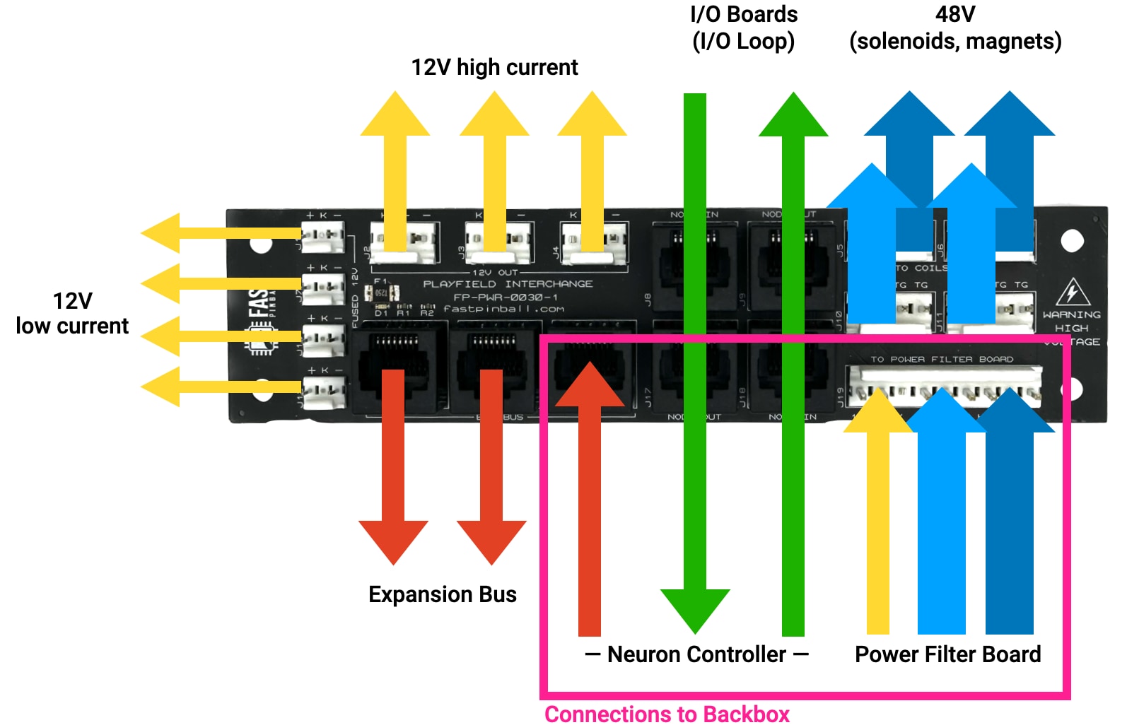
Let's walk through each of the connector types, one by one.
Input power from power filter board in backbox
The FAST playfield interchange board acts as a distribution point for 12V and 48V playfield power. A single 9-pin wiring header J19 receives the main playfield power trunk (including toxic ground) from the smart power filter board. See the Smart Power Filter Board wiring guide for specific pinouts and details of this wiring.
In most cases, you won't need extra terminal connection blocks under your playfield, as the playfield interchange board has several groups of power output headers for various uses. We'll cover them individually.
48V outputs
The playfield interchange board has four headers which provide 48V power and toxic ground. Three of them J5, J6, and J11, use the 48V_1 (H1) power circuit. Each of those have three toxic ground pins as well. 48V header J10 uses the 48V_2 (H2) power circuit, with two toxic grounds. (Why only two? So there can be a key pin to prevent mixing up the H1 and H2 circuits down the road.)
Note
More photos and diagrams of the playfield interchange board are on its product page.
The full details of how to where these 48V playfield wires go are covered in the coil wiring and magnet wiring guides. The general intention is H1 is used for most playfield things (including flippers), while H2 is used for extra high-current or other things you'd want to isolate, such as magnets. (You can use H2 for anything you want if you don't have magnets in your machine.)
If you're actually wiring up your interchange board as you follow along this guide, this 9-pin connector from the smart power filter board is all you need for now.
12V (high current)
There are three 12V high current outputs, J2, J3, and J4. (You know these are high current because they are the larger size 0.156" headers.) These headers are rated up to 7A each.
You'll use one of these headers to provide power to the expansion board which powers your playfield LEDs. (That expansion board generates the 5V for the LED chains from this 12V power.)
12V (low current)
There are four 12V low current (with the smaller 0.100" headers) outputs which can be used to power opto emitters or other low current 12V devices. (Really this is most likely just opto emitter LEDs or boards of opto emitter LEDs.)
For example, typical boards receiving power from these low-current 12V headers include:
There's a 2.5A self-resetting fuse on the interchange board which protects these outputs. This is enough current to power about 200 opto LEDs coming from FAST boards (which are very efficient), or about 50 LEDs when used with resistors to set their voltage. (Remember this is 2.5A at 12 volts, so if you're mentally adding up LED current ratings, the current consumed by the LEDs is at their forward voltage which is well under 12V.) For example, the FAST trough opto emitter consumes about 100mA at 12V, and the FAST 4-channel opto emitter consumes about 43mA at 12V.
You should use at least 22 gauge wire since you want to support at least 2.5A. (Remember from the guide to fusing that we want the fuse to be the weakest link in your circuit, so if the fuse if 2.5A, your wire needs to support at least 2.5A as well.)
I/O Loop passthrough
The playfield interchange board includes RJ-45 pass-through jacks for the I/O Loop. These jacks are just like Ethernet cable couplers, in that they just pass straight through. In fact the "out" and "in" directions don't matter. (Just know that each jack is connected to the one behind it, not next to it. The green arrows in the diagram above show this.)
One of these I/O Loop cables will go up to the Neuron controller in your backbox, and the other will go down to your cabinet I/O board.
The other two jacks for the I/O Loop will connect to your playfield I/O boards whose wiring is covered in the next guide.
Expansion bus breakouts
Finally, there are three jacks for the FAST Expansion Bus which are wired together. These three ports are interchangeable, and it does not matter which boards are plugged in where.
One of these ports will go back to the Neuron controller in your backbox. Another will connect to the expansion board on your playfield running the LEDs. The third one could be used for an additional playfield expansion board (some kind of very cool toy?), or it could go to the cabinet for something like a shaker or cabinet lighting.
Many FAST expansion boards have multiple expansion ports and can be daisy chained as needed. So the specifics of which expansion port goes where on this board really will depend on your machine. The specifics of your machine will also dictate whether 1 or 2 cables will need to be disconnected here to remove the playfield from your machine.
Make sure your cables are long enough!
As mentioned in the smart power filter board wiring guide, it's very important that you ensure the wires that connect your playfield to your machine are long enough.
In addition to ensuring the backbox can fold down (it's way longer than you think!), since this board is on your playfield, you also need to ensure your cables are long enough to make sure your playfield can stand up. And remember this could include wires to your backbox and cabinet.
N or > jump the next page, P or < for previous, search with S or ?