How to wire solenoids & drivers in a FAST Neuron-controlled pinball machine
Wiring, high voltage, and electricity can be dangerous. Read this first!
The voltages and electricity discussed here can be dangerous and could cause property loss or death. It is your responsibility to ensure you are aware of these risks and comfortable with these processes. Furthermore your local jurisdiction may have regulations or rules which differ from what we discuss here, including wiring colors, standards, techniques, etc. Although based on broadly adopted methods, FAST Pinball does not employ Professional Engineers and this information is not professional recommendations. There may be errors, omissions, or typos here. Any pinball machine available to the general public should be reviewed by a licensed Professional Engineer in your region. Use this content at your own risk.
This guide explains how to wire drivers when you're using the FAST Pinball Modern Platform. Drivers are typically solenoids (also called "coils"), but could also be magnets or motors or other on/off type devices. In this guide, we'll focus on solenoids specifically, with future guides that will discuss the specifics for motors, magnets, and other things power by driver outputs of a FAST I/O board.
In FAST Neuron-controlled modern machines, your drivers run on 48V. Machines from decades ago used different voltages, including 70V DC for original WPC-era machines, but the industry has moved to 48V as it is technically considered "low power" and is not as strict with the wiring regulations. And it's safer in general.
Note that in the days before LEDs, drivers were used to control flashers and general illumination (GI). In FAST modern machines, those are mostly replaced by regular RGB LEDs. (That said, the cabinet I/O board uses special low current drivers to control single-color cabinet LEDs).
How a FAST I/O board fires a solenoid
Wiring your solenoids will make more sense if you have a solid understand of how a FAST I/O board actually fires a driver. So to do that, let's imagine the simplest driver circuit possible.
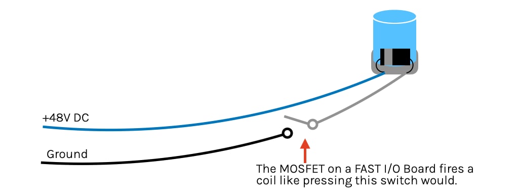
In the drawing above, +48V DC is always on and goes to the solenoid (blue wire). The solenoid is juiced at all times and just ready to fire—it just needs a connection to ground. That ground connection coming off the solenoid (gray wire) goes to one leg of a simple switch, and the other leg of that switch (black wire) goes back to the ground (negative) side of that +48V DC. This is the simplest circuit possible. Push the switch, solenoid fires!
This is exactly what the FAST I/O board does to fire a coil. The only difference is that instead of a mechanical switch, it's an electrical switch (in the form of a MOSFET transistor). But you could imagine it like this:
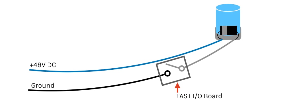
If you have two solenoids attached to an I/O board, the following diagram shows how they would be hooked up.
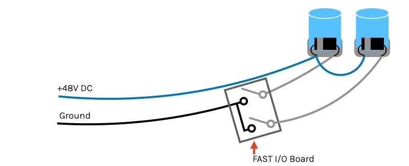
Notice that the blue 48V supply wire is common among all solenoids. You can daisy chain one to the next since this is just providing uncontrolled power.
The gray wire is the actual control line used to fire the coil. So each solenoid has its own one of these going back to the numbered driver control pin on the I/O board.
Finally, the black wire is the toxic ground return, which connects the other end of the driver control line on the I/O board back to the playfield interchange board.
| Color | Path | Purpose |
|---|---|---|
 Blue Blue |
Playfield Interchange Board to every solenoid | 48V always on |
 Gray Gray |
Solenoid to driver control on I/O board | Fires coil |
 Black Black |
I/O board to Playfield Interchange Board | Toxic Ground Return |
The 48V ground is TOXIC! Do not mix with 12V ground!
Before we start wiring any drivers, we need to revisit the concept of toxic ground. Recall from our guide to grounds and grounding (which you definitely read, like for real actually read, right?) that when a high-current load (like a solenoid) is activated, the resistance in the circuit causes the supply voltage to drop and the ground level (which is supposed to be zero volts) to rise. This happens in all circuits (since in the real world they all have resistance), though the 12V and other circuits in your machine don't experience this current fluctuation, so the ground rise is so small it doesn't matter.
But with solenoids, their ground returns can fluctuate by one volt or more, which is not noticeable on a 48V circuit, but a really big deal on a 12V circuit!
Because of this, it is CRITICAL that the ground lines for your solenoids and drivers are NOT connected to any other ground lines in your machine. (They only connect via the internal circuitry in the smart power filter board.) This ground separation is so important that we call the 48V grounds "toxic grounds", and we show the pink fuzz around them in our drawings.
So going back to our simple coil circuit from before, this is a more accurate representation of what's happening in real life:
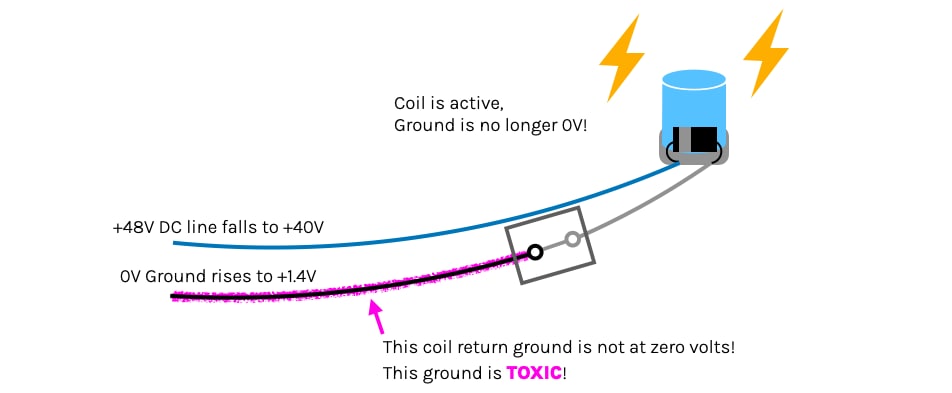
When that high load coil is activated, the instant rush of all that current over those wires with resistance will cause the +48V line to drop, and the (toxic) ground line to rise above zero. When the high current driver is turned off, the whole thing happens in reverse and the toxic ground drops below 0V.
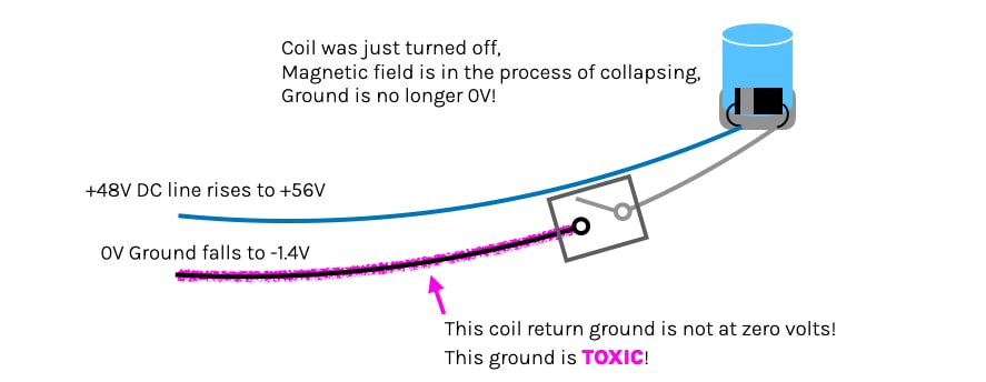
And remember this ± 1.4V (or more) swing on the toxic ground happens constantly, any time a solenoid is fired or released (not just from the high current ones). Multiply that by all your drivers in your machine, and you can see how toxic that ground is and how it would screw up electronics not designed for it. So keep everything else away from that toxic ground and you'll be fine.
How do FAST I/O boards handle toxic ground?
A quick little sidebar for those who might be curious: If the toxic ground is so dangerous to electronics powered by lower voltages, how do the I/O boards themselves handle it without getting damaged?
The ground of each FAST I/O board is designed to float. In other words, the solenoid firing action causes the ground on the I/O board to move above and below zero, as it would on any board, but the logic and processor parts of the I/O board will safely float with it. So at any given moment, all the I/O boards in your machine will have different ground references based on what's happening to their drivers at the moment. This is why you must connect both legs of a switch to the same I/O board, because you don't want a path to connect the ground of one I/O board to another.
Wiring solenoids to FAST I/O boards
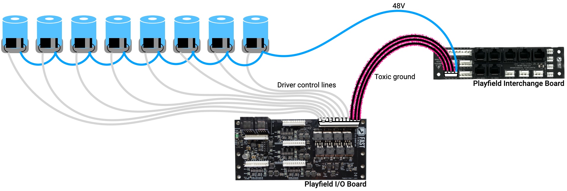
Now that you understand the theory of how solenoids are controlled, let's look at how they're actually wired to a FAST I/O board. The following diagram shows this:
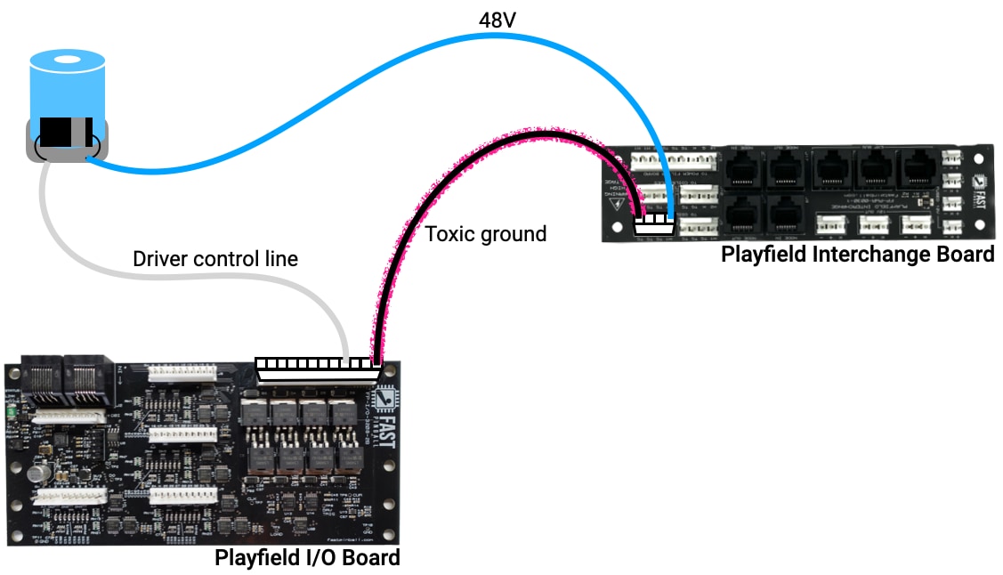
All playfield power comes from the playfield interchange board, including the always-on 48V and toxic ground returns. (The the wiring guide for the playfield interchange board for more details.)
An actual solenoid is wired to an I/O board just like the theoretical drawings above. The 48V goes to the solenoid lug on the same side as the diode stripe. The other lug goes to one of the numbered driver control lines on an I/O board, and the ground output of the I/O board goes back to the toxic ground pins on the playfield interchange board.
If you look at a close up of a driver control header on an I/O board, it will look something like this:
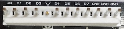
The D0 through D7 are the eight different driver control lines on this header. These will correspond to the specific driver number mappings you'll use in your game software. (See the FAST Modern Platform driver documentation for an explanation of how the numbering works.)
You'll also notice there are three GND pins. Since this toxic ground connection is what moves that massive amount of current needed to fire a solenoid, if you have more than one high current solenoid connected to the same I/O board, you'll need more than one toxic ground wire to handle it all. (More on this in a bit.)
Do you need diodes on coils? Yes!
All solenoids and magnets require diodes. Period.
Coils are inductors, meaning when you send them electricity, they turn it into a magnetic field. But they operate in reverse too. If you send them a magnetic field, they're convert it back into electricity. So when a solenoid is active in a pinball machine, the 48V from the I/O board provides the electrical pressure to keep that magnetic field from entering the coil. But when the electricity is cut off, there's nothing to prevent that coil from sucking up that magnetic field, which it happily does, converting it into electricity which then flies in the wrong direction down the wires into the I/O board.
We designed the FAST I/O boards with as much protection as practical. (For example, this aspect of that protection includes transient voltage suppressors.) But FAST I/O boards support a wide range of usage scenarios, and every machine is different, you need to install diodes across each solenoid's lugs in your machine. (These are called flyback diodes.)
For regular solenoids, we suggest either 1N4001, 1N4004, or 1N4007 diodes. (The difference between those diode types is the max voltage rating, but they're all above 48V so it doesn't matter which you pick.) They only cost a few cents each. Install the diode so the side with the stripe is facing the positive (blue wire from your power filter board) wire. Solenoids do not have polarity, so you need the diode stripe and blue wire to be on the same lug, but which lug of the coil that is doesn't matter.
(Diodes and lugs for dual wound coils are covered in the flipper wiring guide.)
By the way, you might be slightly confused because switches in the FAST Modern Platform do NOT require diodes (since they're all direct and there's no switch matrix). So if you're thinking, "I thought FAST didn't need diodes", that's NO diodes for switches but YES diodes for coils.
Adding a second solenoid
Now that you see how a solenoid is wired to an I/O board, let's look at how you add the next one. The drawing below shows this:
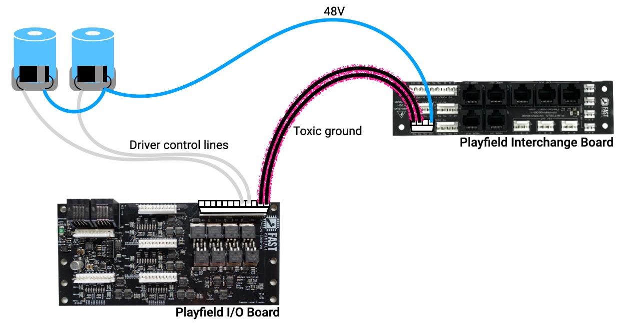
You don't need a new 48V wire since all it's doing is providing the supply voltage, so you can just daisy chain the connection from the lug of your first coil, ensuring you diode is installed so that its stripe is facing the same lug you're connecting this blue 48V wire to.
For the gray driver control line, that just goes from the other solenoid lug to another driver control pin on I/O board.
Notice, though, that we also added a second toxic ground return to the playfield interchange board. You don't always have to do this, and we'll cover how to calculate how many you need in a bit. But we include it here in this illustration to reinforce the concept that you will need to add more toxic grounds as you add more solenoids.
Adding lots of solenoids to the same I/O board
You can play out this process to fill the rest of the I/O board with solenoids. The wiring is similar:
But there's a caveat, in that once you start adding a lot of solenoids, you have to start to wonder if that single blue 48V supply wire has enough capacity.
We like to visualize electrical wiring like water pipes. The more plumbing fixtures added to a line, the larger the pipes need to be. Same with wiring. More "stuff" on a wire requires a bigger wire. Since moving to a physically larger diameter wire is impractical, we handle this instead by just adding additional parallel wires. This is exactly why we used three 48V sets of wires from the power supply to the filter board.
In your actual machine, you'll run multiple 48V wires from the playfield interchange board to ensure that no single wire will be stressed by too many things at once. Here's a quick example where we added a second 48V wire, which means each wire is only supplying power for 4 solenoids instead of 8.
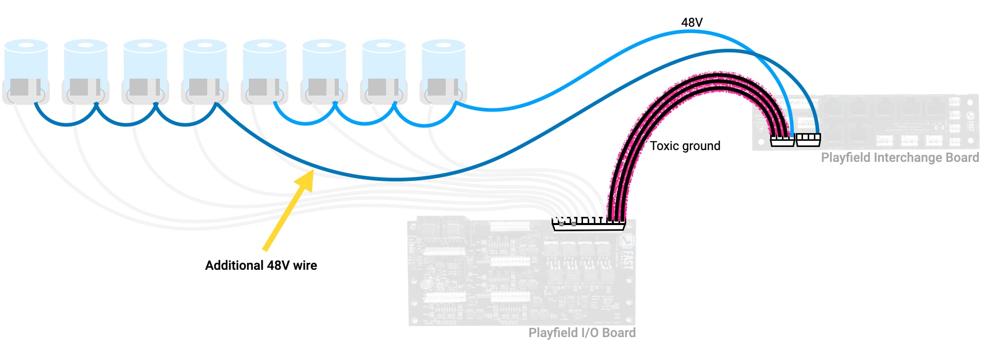
How many solenoids can each 48V wire support?
The playfield interchange board has a total of four 48V output headers: 3 for the 48V #1 circuit, and 1 for the #2 circuit.
A big pinball machine could have, what, 30 drivers? With only four 48V supply wires, each supply wire would be powering 7 or 8 different solenoids. That's fine! A single 48V supply wire could support 20 or more solenoids, because it's not about "how many", rather, it's "how many are fired at the same time?" Actually, we can refine that further and say it's, "how many high current things will be fired at the same time?"
High current coils include:
- The power winding of any dual-wound coil (flippers, some diverters)
- Magnets
- 48V Shaker motors (most shaker motors are 12V now so this probably isn't you)
- Drop target resets (maybe? depends how many targets and how large the coil is)
- Big diverters
- Others? Maybe?
Our rule of thumb is you should only have 2 high-current solenoids per 48V blue wire run. The lower current coils (which are everything else: trough, VUKs, pops, slings, diverters, little playfield motors, the flipper hold windings, etc.) don't matter in this calculation. You can have as many lower current things on a 48V line which already has its 2 high current ones.
For example, if you have 2 flippers (4 drivers, 2 power and 2 hold windings), you could also put the slingshots, tough eject, kickback, auto launcher, and more on the same 48V wire.
Any 48V supply wire can go to any solenoid connected to any I/O board.
How many toxic grounds should each I/O board use?
As you can probably guess, there's a similar conversation about balancing out the toxic ground side of circuits. (Going back to the plumbing analogy, if you have a lot of fixtures and large supply lines, you need to scale up your drain lines to match.)
The toxic grounds run from the I/O board back to the playfield interchange board. Every I/O board has multiple GND outputs for this. You must connect at least one or else none of the drivers attached to that board will work. (While this sounds obvious, more than one of us have wondered why our flippers don't work only to realize we didn't connect the I/O board back to toxic ground.)
So, every I/O board requires at least one, but they also support more (up to 6, depending on the board). So how many of those do you connect?
- One toxic ground per high current solenoid from that I/O board.
- One toxic ground to cover "everything else" from that I/O board.
So in our example from above, with a single 48V wire covering the flippers and other lower third mechs, if all those solenoids were connected to the same I/O board, you would run 3 toxic ground wires: 2 for the two flipper power windings and 1 for everything else.
Finally, know that each FAST I/O board has a large ground plane that connects all the toxic ground pins together. So if you have an I/O board with multiple driver headers, you can consider the GND pins from all headers on the board to be the same, and it doesn't matter which sets of pins you use. If you have 3 coils simultaneously firing from the first header, and three toxic ground lines connected to the second header, that's fine.
N or > jump the next page, P or < for previous, search with S or ?