FAST Nano Controller (Retired)
Part Number: FP-CPU-003
This product is retired
The Nano Controller is now retired. The current version is the FAST Neuron Controller.
The FAST Nano Controller is the interface between your newly-built pinball machine powered by the FAST Modern Platform and the controlling host computer which runs your game software.
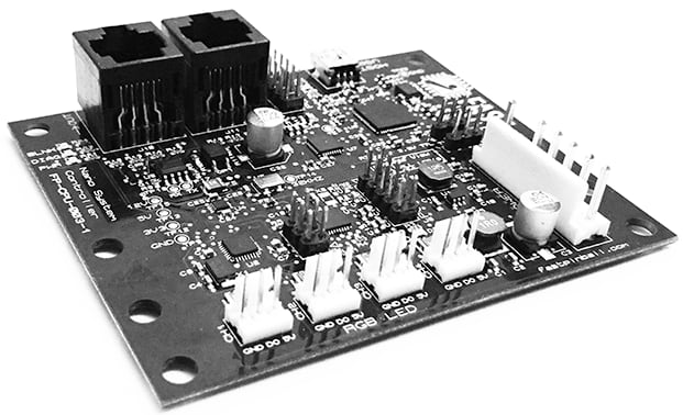
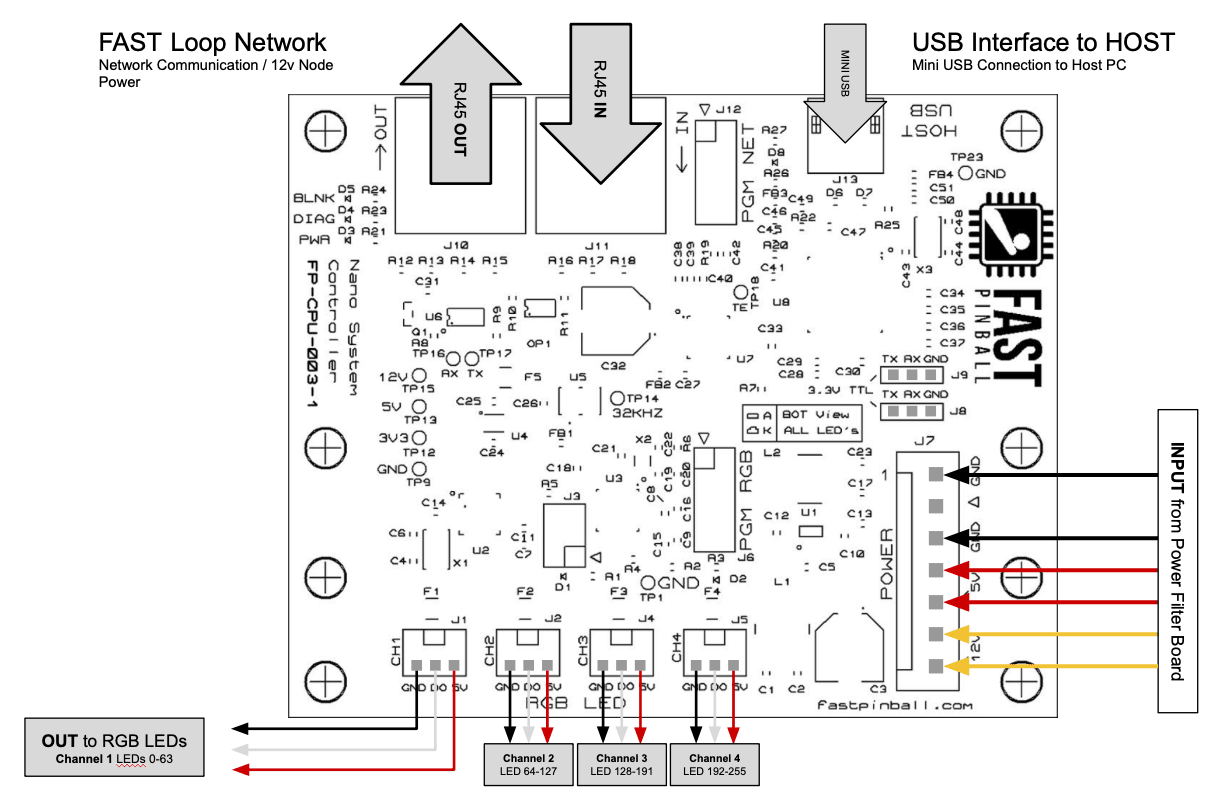
The FAST Nano Controller connects to FAST I/O boards using RJ-45 cables in a loop which form the FAST I/O Loop. It also drives up to 256 RGB LEDs. A 7-pin power connector feeds the controller 5 volts, 12 volts, and universal ground.
Features
- Drives 4 strands of up to 64 serial RGB LEDs each (for 256 RGB LEDs total)
- Interfaces with FAST I/O driver boards to control devices and read switches
- You can connect up to 9 I/0 Boards with a maximum of 120 switches and 120 drivers
- Automatically distributes 12v power to connected I/O boards
- Sends 5V power to the serial LEDs.
- USB interface connects to a controlling host computer and presents virtual serial ports. (No drivers or software libraries are needed. Details below.)
Serial Interface
The FAST Nano Controller contains multiple microprocessors. One processor controls the FAST I/O Loop of FAST I/O boards used to read switches, fire coils, and much more. Another processor controls up to 256 serial RGB LEDs.
A controlling computer connects to the FAST Nano Controller using a USB mini cable. When you connect to the controller via USB, four new virtual serial ports appear. (This is automatic, no drivers are needed.)
The four serial ports function as follows:
| Port | Processor | Description | Baud |
|---|---|---|---|
| Port 1 | Not Used | ||
| Port 2 | NET | FAST I/O Loop Processor | 921600 |
| Port 3 | RGB | RGB LED Control | 921600 |
| Port 4 | Not Used |
Note that the port numbers in the chart above indicate the relative order of the virtual ports that appear when you connect the Nano to your computer. The exact names / numbers will depend on your specific computer. (For example, on Windows they are typically named COM3 - COM7. On Mac they will be like usbserial41xxx.)
The controlling PC communicates with each processor by making a virtual serial port connection and then using the FAST Serial Protocol to send and receive commands and status messages. (Most of these as ASCII, meaning you can interact with your pinball machine via a terminal emulator!)
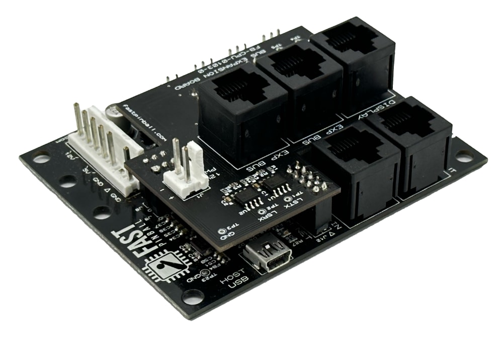
Adding support for Expansion and Display Busses
The Nano was created before the FAST Expansion Bus and Display Bus existed. We have an Expansion Hat you can use to add support to an existing Nano. Details here.
Firmware Updates
Both the NET and RGB processors on the Nano have updatable firmware. Check our firmware page to see the latest versions and learn how to update your Nano if needed.
Tutorials & Learning
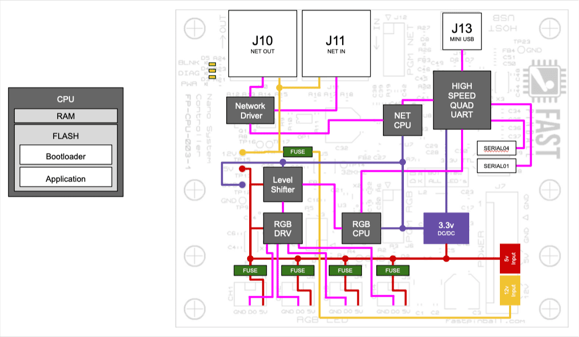
Block Diagram
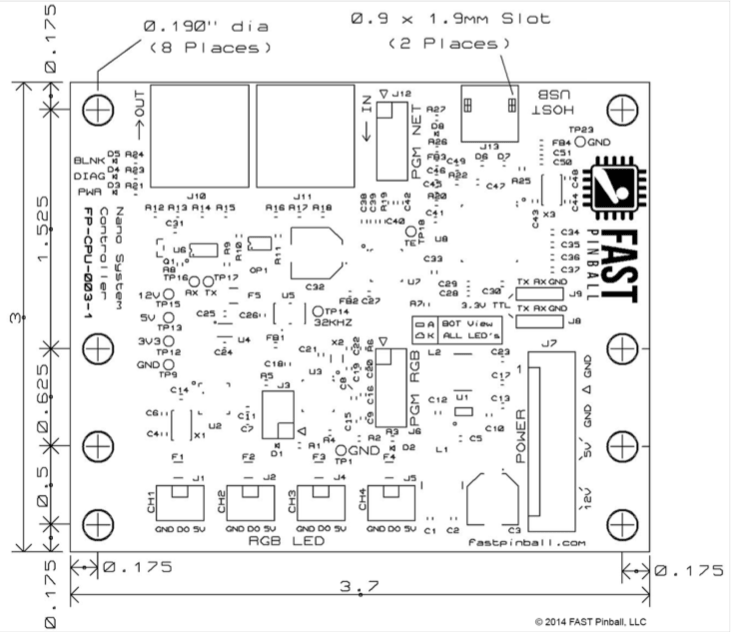
Mechanical Diagram
All dimensions are in inches.
Wiring Diagram
Wiring Guides
Refer to our series of guides on pinball machine wiring for details on how to wire the FAST Nano controller to the various LEDs and I/O boards in your machine.
Connector Housings Needed
- 7 Pin .156" Female Connector for power input
- 3 Pin .100" Female Connector (4) for serial RBG LED strands
- RJ-45 jacks (2) for FAST I/O Loop connection to driver boards
Header & Connector Pinouts
| J1 | PIN | RGB LED Channel 1 – LEDs 0-63 | 3-Pin .100″ |
|---|---|---|---|
| GND | Ground | OUTPUT | |
| DO | Data Out | OUTPUT | |
| 5v | Fused 5 Volts | OUTPUT |
| J2 | PIN | RGB LED Channel 2 – LEDs 64-127 | 3-Pin .100″ |
|---|---|---|---|
| GND | Ground | OUTPUT | |
| DO | Data Out | OUTPUT | |
| 5v | Fused 5 Volts | OUTPUT |
| J3 | PROGRAMMING | 2×3-Pin .100″ |
|---|---|---|
| Device Programming | INPUT/OUTPUT |
| J4 | PIN | RGB LED Channel 3 – LEDs 128-191 | 3-Pin .100″ |
|---|---|---|---|
| GND | Ground | OUTPUT | |
| DO | Data Out | OUTPUT | |
| 5v | Fused 5 Volts | OUTPUT |
| J5 | PIN | RGB LED Channel 4 – LEDs 192-255 | 3-Pin .100″ |
|---|---|---|---|
| GND | Ground | OUTPUT | |
| DO | Data Out | OUTPUT | |
| 5v | Fused 5 Volts | OUTPUT |
| J6 | PROGRAMMING | 2×5-Pin .100″ |
|---|---|---|
| Device Programming | INPUT/OUTPUT |
| J7 | PIN | POWER INPUT | 7-Pin .156″ |
|---|---|---|---|
| 12v | 12 Volts | INPUT | |
| 12v | 12 Volts | INPUT | |
| 5v | 5 Volts | INPUT | |
| 5v | 5 Volts | INPUT | |
| GND | Ground | INPUT | |
| \/ | KEY | N/A | |
| GND | Ground | INPUT |
| J8 | PIN | SERIAL COMM 01 | 3-Pin .100″ |
|---|---|---|---|
| TX | Transmit Data | OUTPUT | |
| RX | Receive Data | INPUT | |
| GND | Ground | GROUND |
| J9 | PIN | SERIAL COMM 04 | 3-Pin .100″ |
|---|---|---|---|
| TX | Transmit Data | OUTPUT | |
| RX | Receive Data | INPUT | |
| GND | Ground | GROUND |
| J10 | I/O Loop OUT | RJ45 – CAT5e/CAT6 |
|---|---|---|
| 1 | COM ENABLE | OUTPUT |
| 2 | GROUND | GROUND |
| 3 | Fused 12v | OUTPUT |
| 4 | COM- | OUTPUT |
| 5 | COM+ | OUTPUT |
| 6 | Fused 12v | OUTPUT |
| 7 | GROUND | GROUND |
| 8 | GROUND | GROUND |
| J11 | WIRE | I/O Loop IN | RJ45 – CAT5e/CAT6 |
|---|---|---|---|
| 1 | COM ENABLE | INPUT | |
| 2 | GROUND | GROUND | |
| 3 | Fused 12v | OUTPUT | |
| 4 | COM- | INPUT | |
| 5 | COM+ | INPUT | |
| 6 | Fused 12v | OUTPUT | |
| 7 | GROUND | GROUND | |
| 8 | GROUND | GROUND |
| J12 | PROGRAMMING | 2×5-Pin .100″ |
|---|---|---|
| Device Programming | INPUT/OUTPUT |
| J13 | HOST USB | MINI USB |
|---|---|---|
| Connection to the Controlling PC | INPUT/OUTPUT |
N or > jump the next page, P or < for previous, search with S or ?