How to wire your Smart Power Filter Board in a FAST Neuron-controlled pinball machine
Wiring, high voltage, and electricity can be dangerous. Read this first!
The voltages and electricity discussed here can be dangerous and could cause property loss or death. It is your responsibility to ensure you are aware of these risks and comfortable with these processes. Furthermore your local jurisdiction may have regulations or rules which differ from what we discuss here, including wiring colors, standards, techniques, etc. Although based on broadly adopted methods, FAST Pinball does not employ Professional Engineers and this information is not professional recommendations. There may be errors, omissions, or typos here. Any pinball machine available to the general public should be reviewed by a licensed Professional Engineer in your region. Use this content at your own risk.
This guide continues our step-by-step wiring guide series for Neuron-controlled pinball machines and focuses on the FAST Smart Power Filter Board (Part number: FP-PWR-0007) wiring.
By this point, you should have read our other guides on AC power wiring and the optional soft power control option. Now you're ready to wire the DC outputs of your power supplies to the FAST Smart Power Filter Board, and to figure out your power transmission strategy for your machine.
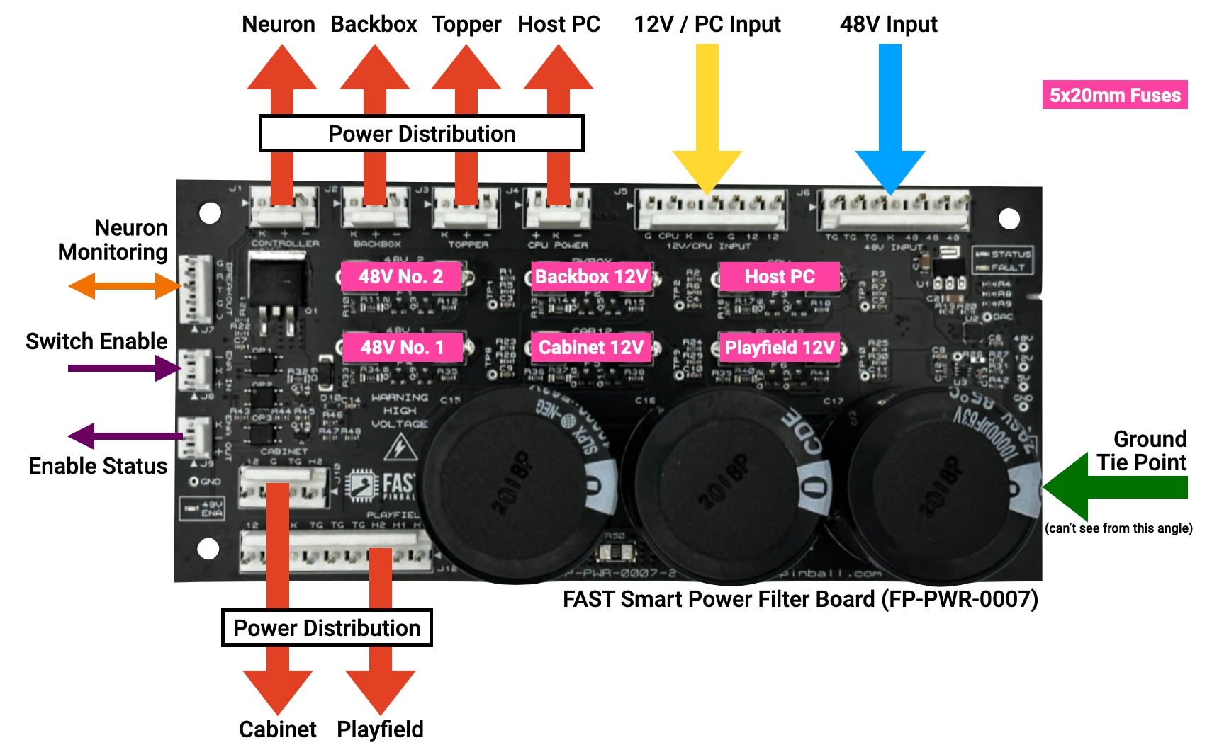
Let's start by looking at the FAST Smart Power Filter board for Neuron-controlled machines. You can refer to the product manual for details, including more explanations of features, full pinouts, schematics, etc. The wiring guide you're reading now is more focused on how to integrate it into your machine versus the specifics of the board.
What does the Smart Power Filter Board do?
The FAST Smart Power Filter Board is the interface between your power supplies and the rest of your machine. It takes the raw DC power output from your power supplies, breaks it into branch circuits, adds fuses, holds reserve tanks for the 48V (those three large capacitors), provides a high-current, low-resistance DC ground tie point, and adds remote control and monitoring via an onboard microprocessor with a connection to one of the breakout ports on the Neuron.
These capacitors will hold their charge after power is removed
Since capacitors are used to store electrical energy, they will hold their charge after power is removed. The FAST Smart Power Filter board has circuitry which will discharge these capacitors once power is removed, but this happens slowly over several hours. Always treat large caps as if they're charged!
This "Smart" Power Filter Board is an update to the initial Power Filter Board which has been specifically designed for FAST Neuron-controlled pinball machines. If you've wired up a Nano-controlled machine in the past, the old FAST Power Filter Board is similar (Part number: FP-PWR-005), though technically a different and non-interchangeable board with this one.
Let's walk through all the connections to this board, one-by-one.
48V power supply input
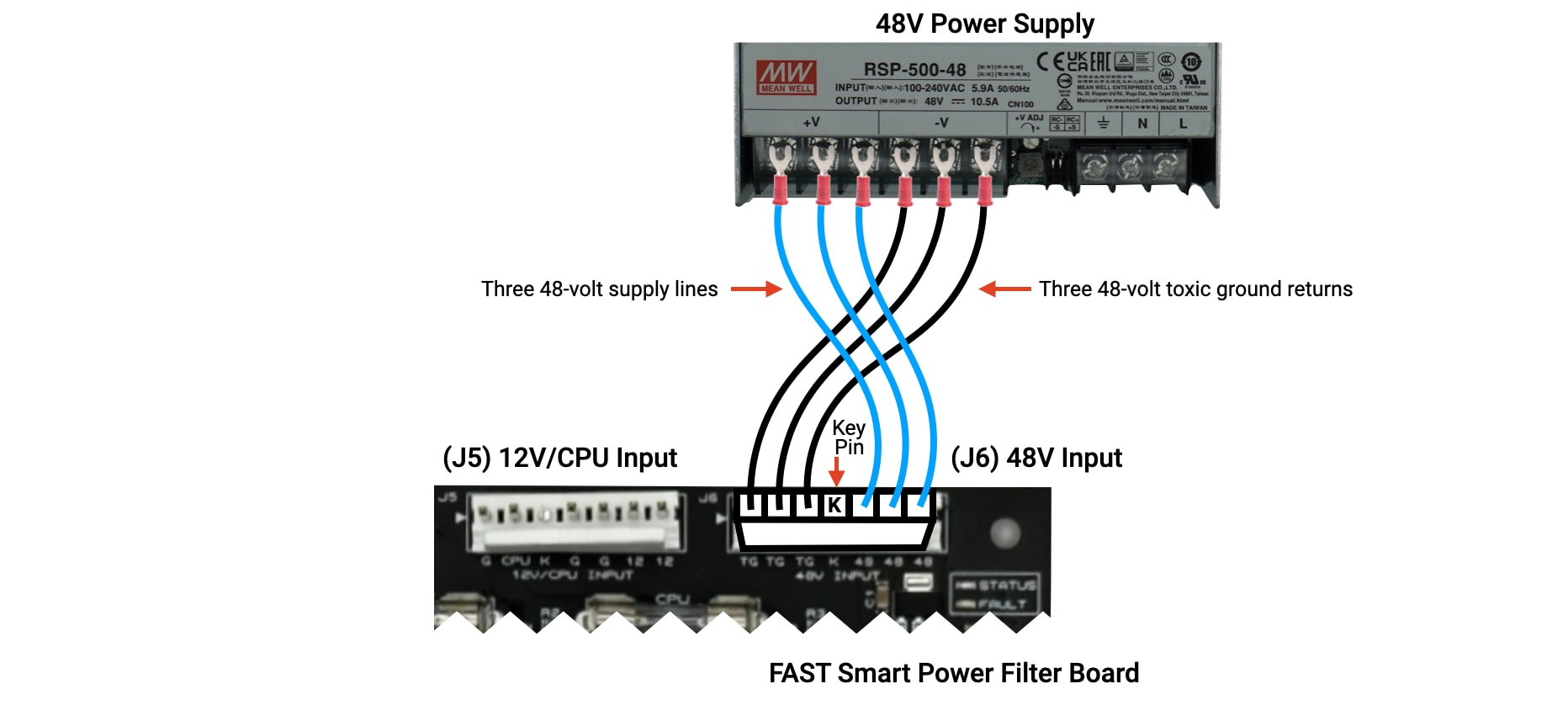
The first connection we'll look at is the 48-volt input connector J6 labeled 48V INPUT in the upper right corner of the Smart Power Filter Board. This is where you connect the 48V output from your power supply. This is a 7-pin, 0.156" header, so you'll need to get a 7-pin, 0.156" female connector housing and pins to assemble it. (What type of wire do you use? This is covered in our guide to wiring standards)
Make a custom cable with the 7-pin female connector on one end for the filter board input and fork spade connectors crimped to the wires on the other end to connect to your power supply DC outputs. You'll have 3 black 18-gauge wires going into the first three pins, then a blank key pin, then 3 blue wires to pins 5-7. (Refer to our guide to pinball wiring standards for details of why we suggest these colors and gauges.)
Speaking of the key position, we highly suggest that you buy the key plugs to stick in the female connector pin location which corresponds to the missing pin on the board's header. Since the key pins are in different locations on each connector, this will help ensure you (or someone else in the future) doesn't plug the wrong connector into the wrong header. (For example, both the 48 volt and 12 volt headers are 7 pins, so those key plugs will prevent future you from making a preventable mistake in the future!)
Finally, note that we refer to the 48-volt ground wires as "toxic grounds," as they are not interchangeable with the 12-volt "logic grounds". We will cover the full details of this in the driver wiring guide, but for now just know that 48V and 12V grounds are separate sets of wires in your machine and only connect to each other within the Smart Power Filter Board.
Do you have to use 3 of each wire?
Yes.
You'll notice the 48-volt power supply output has three terminals for V+ (48 volts, blue wire), and V- (black toxic ground return). You'll also notice the filter board has three header pins for each (TG for toxic ground, and 48 for 48 volts). Having three of each is by design, and you must use them all so you end up with three parallel wires of each.
If you're wondering why, read on. (Or just use three of each and skip to the next section.)
Remember from the intro guide to grounding that wires are just really long and bendy resistors, and also that when you have high current demands (like when a flipper flips), that resistance causes the voltage to drop. Those three large capacitors act as a reserve tank to dump their electrons into the circuit to counteract this, but when that happens, the power supply also needs to kick into gear to provide enough power to re-fill those caps. (This is typically when the power supply fan kicks on.) So having three of each wire from the power supply is like having three lanes of traffic instead of one--it simply allows more power to move faster. (In theory you could just have a single extra fat wire, but that requires different connectors and terminals which is why tripling up the wires is the easiest option.)
The other reason we want multiple wires is because the wire gauge and connectors in a FAST Pinball modern machine are rated up to about 7A, but if you have multiple flippers active at the same time, they could (for a very brief time) draw more than 7A. And your power supply is most likely rated for more than 7A at 48V, so if the system is asking for more than 7A, and the PSU can provide it, we need to ensure that more than a single 7A max wire is used.
This is also helpful if there's ever a short, since we want to ensure the fuses on the filter board are the weakest link in the system and will blow, not the wire from the PSU to the board!
12V power supply input
Once your 48-volt power input is connected, the next step is to connect the 12-volt power supply to its header, J5, labeled 12V/CPU INPUT. This is pretty much like the 48V supply except there's only two of each wire instead of three. (This also conveniently matches the number of screw terminals on the 12V supply.)
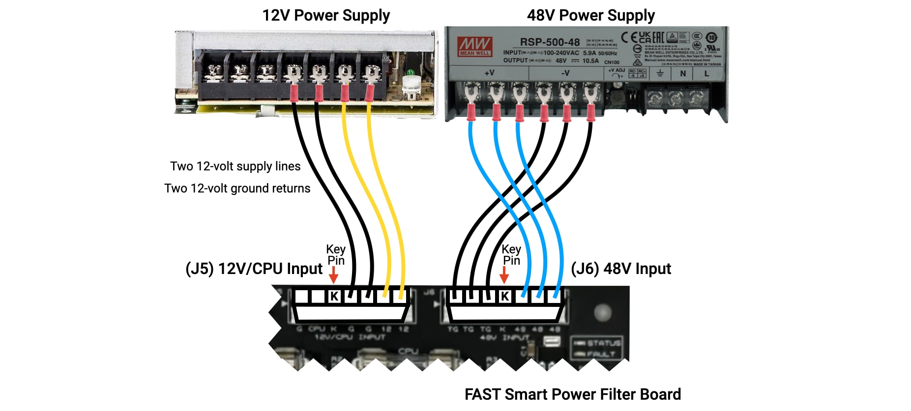
The reason there are only two wires for the 12V supply is something we touched on earlier, mainly that the 12V system in a pinball machine is not as "spike-y" as the 48V. The 12V system doesn't have the same coil and magnet load, and the demand is much smoother in general. (This is why there are no huge reserve capacitors for the 12V circuit, they are just not needed because the PSU is never taxed in that way.)
That said, you still need to run two of each wire for the same safety reasons discussed with the 48V system. There's a good chance that your 12V power supply will be rated above the 7A max of the 0.156" headers on the filter board, so if demand ever exceeds 7A, we want to ensure a safe path to deliver that much current from the power supply.
12V loads over 7A require additional care!
All 0.156" headers on FAST boards are rated for 7A per pin. If your 12V PSU can deliver more than 7A, that's ok since it's spread over multiple wires. But if one of those wires becomes disconnected, you could potentially have more than 7A going into a single pin on the filter board which is undesirable. You might want to add inline fuses to the 12V input side of the filter board to protect your machine in this situation. Consideration for this is covered in our guide to fuses and current draw.
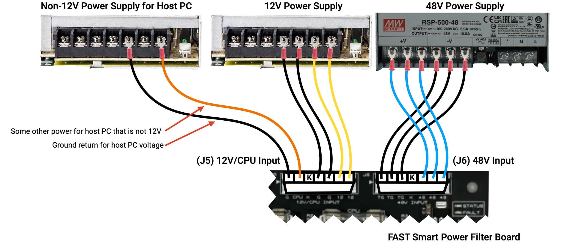
Host PC power supply input
You might notice that the label on the board for the 12V input header is technically written as 12V/CPU INPUT. In this case, "CPU" is shorthand for your Host PC (the computer running the Mission Pinball Framework, or other game software). So this header on the filter board is used for both the 12V power input as well as the power input for your host PC. The host PC has its own pins (pins 1 and 2, G and CPU) in order to provide the flexibility to use a host PC that runs on something other than 12V. (But 12V is fine too of course.) You can use voltage up to 60VDC, but keep the current under 7A.
If you select a host PC that runs on 12V (which is the most common, and what many small form factor PCs like the Intel Nuc use), than that's great, because then you can use your existing 12V power supply. In that case, just run a second 12V and ground line from your 12V supply to the "CPU" pins of J5. (It's ok to double up those spade connectors on the screw terminals.)
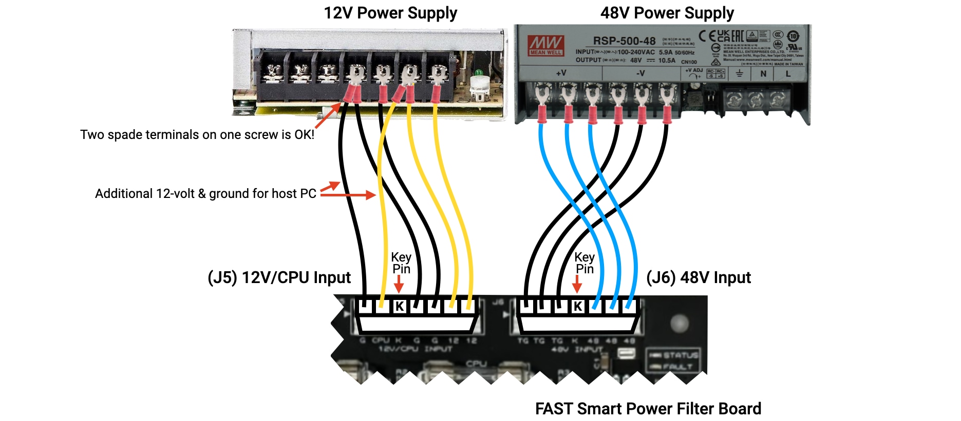
Note that the CPU POWER output header (J4) on the power filter board will output whatever power comes in via the two input pins on J5, so even if you have a 12V host PC, you need to run those lines into those pins too.
If you are wondering if you really need to double up your connectors and have three sets of 12V wires (1 set to the CPU pins and 2 sets to the general 12V pins), the answer is yes, you really need all three.
What if your host PC is not 12 volts?
No problem!
The FAST Smart Power Filter Board is designed so that any DC voltage from about 9-30VDC can be used for your host PC power. So if you have, for example, a 19-volt host PC, you can put the 19V PSU in your machine too and run its outputs to pins 1 and 2 of J5 on your filter board, like this:
In this case, the CPU POWER output header (J4) on the filter board will be 19V, and the CPU fuse (F3) will be 19V and used to protect that line.
If you do this, we suggest a 19V+ wire in some color other than blue or yellow. (There is no standard for this, maybe pick orange or brown, or some other color that you won't confuse in the future.)
DC ground tie point
The FAST Smart Power Filter Board has a terminal spade connector J11 labeled GND TIE which is used to tie your machine's DC grounds (12V logic ground and 48V toxic ground) to chassis and/or earth ground.
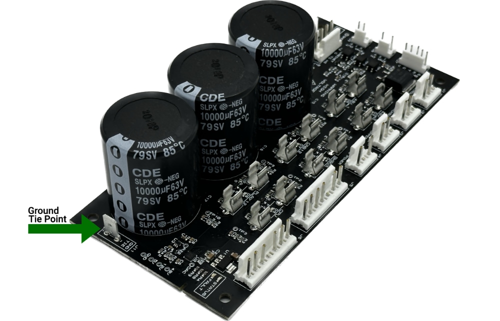
Note that this is not something that you should automatically do as it's a complex decision, and it's covered fully its own guide ("Ground Wiring", it's next). So for now just know that the power filter board safety ties all your DC grounds together, and that if you need to future tie those grounds to other grounds, you would do so via this tab.
Backbox 12V power out
The Smart Power Filter board has a 12V branch circuit for devices located in the backbox, protected by fuse F2 labeled BKBOX. This circuit has three output headers J1, J2, and J3, designed for various backbox-related 12V needs:
J1is labeledCONTROLLERprovides 12V for the Neuron. (The Neuron has its own 12V out which can be used to power additional boards, such as the FAST Audio Interface.)J2is labeledBACKBOXwhich is meant to provide 12V to other things in your backbox, such as the DMD or LCD.J3is labeledTOPPERand could be used to provide 12V to a FAST expansion board in a topper, or any other 12V needs if a topper is not present.
Here's how this might look in the context of your machine:
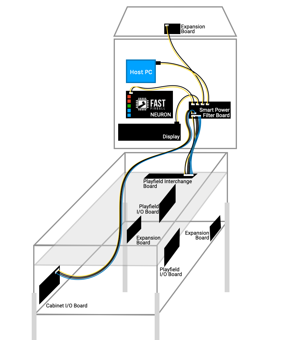
Wiring this up is pretty straightforward. If you need power for other things, you can always wire one of these headers to a terminal strip or whatever else you want. Strictly-speaking, the labels don't mean you have to use them for that purpose.
Just keep in mind that the FAST Smart Power Filter Board is not designed to deliver more than 7A on any one of these branch circuits. (The upcoming guide to fuses and current calculations covers this in depth.)
Host PC power out
The Smart Power Filter Board has a dedicated branch circuit to provide power to the host PC running your game code. This circuit is powered by whatever voltage comes in J5 pins 1 & 2 and is discussed in the Host PC Power section above. It's protected by fuse F3 labeled CPU, and its output header is J4 labeled CPU POWER.
We mentioned just above that this host PC power path is not connected to other 12-volt circuit, even if the host PC is using the same 12 volt input. So if in the future you ever find yourself 12V-constrained, there's almost certainly extra power available from this J4 "CPU" header.
The other end of this host PC power wire will be whatever your specific computer needs. Most likely it's a barrel connector which you can splice in or otherwise attach as needed.
Is using this host PC power out required?
No. For example, maybe you have a Raspberry Pi plugged directly into the Neuron?
If you have a host PC which you do not want to power through the smart power filter board, that's ok. (There's even a bonus of freeing up another 12V power source with lots of current.)
Powering your host PC some other way is fine, but just make sure it's fused! For example, you could connect that into your AC line-in wiring, but whatever DC wires run from that power supply to your host PC need to be fused appropriately just like any other DC power lines in your machine.
Playfield 48V & 12V power out
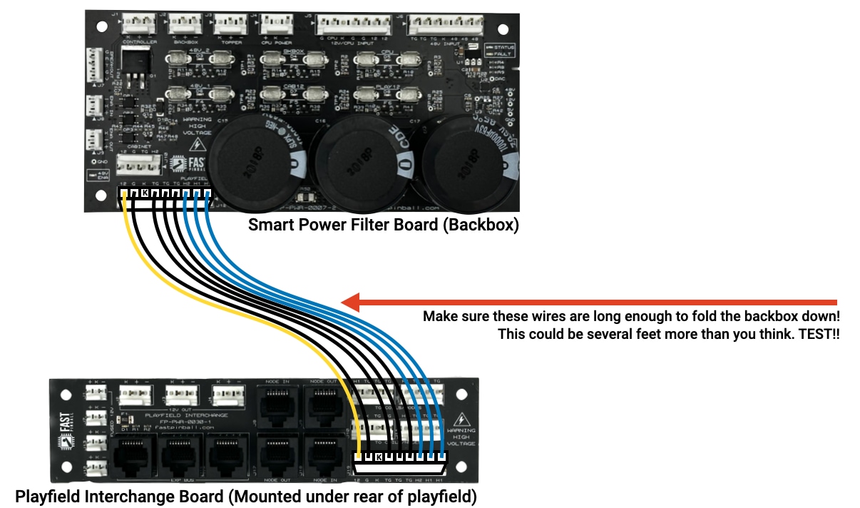
The Smart Power Filter Board has a dedicated 9-pin 0.156" header J12 labeled PLAYFIELD which provides two 48V circuits and a 12V circuit to the playfield.
Fuse F4 labeled 48V_1 is one 48V circuit that protects the 48V on the pins labeled H1, and fuse F1 labeled 48V_2 protects the output of the pin labeled H2. The 12V power output of J12 (pins 1 & 2) is protected by fuse F6 labeled PLAY12.
The Playfield Interchange Board, mounted at the rear of your playfield, has the same 9-pin header to receive that transmission bundle of those three circuits. That interchange board then acts as the distribution point for all playfield power, with lots of 12V and 48V output headers to run to your various playfield boards and mechs.
All that playfield wiring is covered in future guides, so for now just get the 48 and 12 volts to the playfield interchange board, remembering to leave enough length in the cables for the backbox to be able to fold down. (If you haven't actually considered this, backboxes go really far forward when they fold down, and you might need several feet of extra cable slack to allow for this.) Also make sure there's enough slack for the playfield to be lifted up.
You can see how this fits into the overall machine in the diagram in the section above.
Also, yes, you need to use all 8 wires, for the same reasons as the power supply to the filter board trunk lines. These are the main "thoroughfares" of your machine's power, and we need all the lanes! So use 8 wires: 12V, 12V ground, three 48V, and three toxic grounds.
Cabinet 48V & 12V power out
Cabinet power distribution is for the power going into your actual cabinet itself (e.g. not the playfield.) Pinball machines with the electronics and power box in the backbox don't actually have much in the cabinet. At a minimum You'll need 12V to power the I/O board connected to your cabinet switches, and maybe power for your coin door, a shaker motor, and/or a knocker.
The Smart Power Filter Board has a dedicated power output header for the cabinet J10 labeled CABINET. This header contains a dedicated 12V circuit, fuse F5 labeled CAB12, as well as providing access to the 48V circuit protected by fuse F1 labeled 48V_2. (This 48V circuit is shared with the playfield.)
The FAST Cabinet I/O board, which is typically mounted to the left-front corner of the cabinet, has a header to receive these same four power wires from the filter board. So when you're making this wire, allow for enough length for it to reach that board (and again make sure you leave enough slack for the backbox to fold down.)
Smart power management & monitoring (coming soon)
The smart power filter board is "smart" because it has a microprocessor which monitors 48V current draw, reports on whether fuses are good or not, and can remotely enable/disable the 48V. When combined with the Neuron's soft machine power control, the host PC, LCD, and audio control, these capabilities revolutionize the way a pinball machine's power system functions. (For example, now the watchdog can actually cut off 48V supply power, rather than only disabling the control at the I/O boards.)
In order to use these smart capabilities, the power filter board and Neuron need to talk to each other. That's achieved via the header J7 labeled BREAKOUT on the smart power filter board, which you connect to one of the Neuron's expansion breakout headers (any one, doesn't matter) with a short 5-wire cable with 5-pin 0.100" headers.
The code to enable these smart features is not complete yet, so this capability will be added via a future firmware update. (When you update the Neuron's firmware, it also updates the firmware of any attached breakout boards.)
Here's a zoomed-in and cropped diagram of this connection from the Neuron to the smart power filter board:
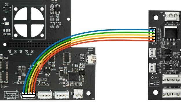
We don't have suggestions for wire colors here, since this is a short cable and you're just wiring the pins straight through. (Use 22 gauge wire for this, like anything else on a 0.100" header.)
You might notice that the the pin descriptions are printed on each board. They are:
GGroundTTransmitRReceiveGGroundVV+
Also note the the T and R pins are swapped between the two boards. This is by design, since the wire one board transmits on will be the other board's receive wire, and vice-versa. So you can wire this up straight through, pin-by-pin. (Pin 1 to Pin 1, Pin 2 to Pin 2, etc.)
48V output enable/disable
The FAST Smart Power Filter Board has the capability to remotely disable its 48 volt output, and to report that to the host computer. Most pinball machines use this feature to cut off the 48V when the coin door is opened, combined with a notification which plays a sound and shows a message letting the player know that the high power has been cut off.
(BTW the "risk" of opening the door without disabling the 48V is not so much getting shocked by the 48VDC, rather it's more about the potential to damage a board if someone sticks a tool in there while the machine is on. Who knows what they might touch or short out? One sneeze and now you need to buy a new board and wait a week for it to arrive. So even on a homebrew, we really like adding this cutoff capability.)
That said, there's actually a decision point to make here, because thanks to the "smart" capability of the FAST Smart Power Filter Board that you wired up in the prior step, you can do all this switch monitoring and 48V cut off in software from the Neuron. (And, frankly, doing it this way enables some other powerful features.)
So, let's walk through both options, and then you can consider which one you want to use in your machine. We'll start with the traditional way:
Option 1. Using physical switches to disable 48V
The FAST Smart Power Filter board has two 0.100" switch headers on the left side. J8 is the ENA IN header and J9 is ENA OUT.
The ENA IN header controls whether the filter board's 48V output is enabled. When pins 1 and 3 are connected, 48V power flows. When they are not connected, the 48V output is disabled. There's an LED below J9 labeled 48V ENA which is lit when the 48V is enabled.
You MUST enable the 48V output, even when testing!
If your power filter board isn't working, make sure the 48V ENA LED is lit. If not, you need to jumper pins 1 and 3 of J8 to replicate a closed enabled switch. Also don't forget the fuse! 😉
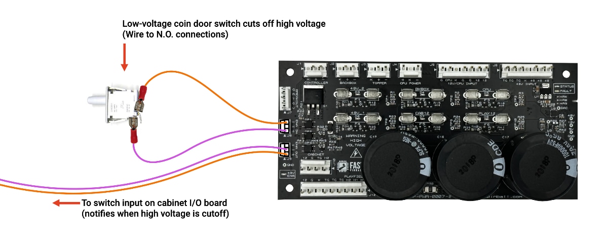
The ENA IN header is intended to be connected to the coin door switch, so when the coin door is opened, the machine's 48V is disabled.
The second switch header, J9, labeled ENA OUT, is a switch output which mirrors the state of the filter board's 48V enabled status. You can use J9 just like any other switch in your machine and connect it up to a switch input on one of your I/O boards. (We suggest the cabinet I/O board since you need to run a line there for the switch anyway, and that's the only switch input location in the cabinet.)
When connecting this to your I/O board, the + is to the numbered switch input (orange wire), and the - is to the common switch ground (purple wire). Then in your machine's game code, you can monitor the status of that switch, and if it's activated, that means the 48V was disabled and you can put that message on the screen or pause the game or whatever else you want to do.
Here's how these two switches would be wired:
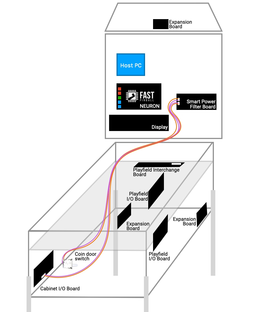
And a look and where they're going in your machine. (click to zoom)
Option 2. Using the Neuron to disable 48V
Now let's look at the modern software-based 48V control which is easier to implement and has several great advantages over the old hard-wired switch method.
This is our preferred method, except for one hiccup: We have not yet released this functionality. The hardware to support it is there. So if you're designing a machine now, you can plan for this, and the Neuron and Smart Power Filter Board hardware support it. We just need to get the code finished which we'll deliver via a future software update. (This isn't too far away, thinks months, not years.)
So if you want to plan to use the Neuron to control the 48V output, that's great. You'll find that the wiring is much simpler. You will not use the ENA IN or ENA OUT headers at all. (Instead that 5-pin breakout connection between the Neuron and Smart Power Filter Board handles the communication.) As for the physical switch for your coin door, you'll still need that, but instead of running that switch from your coin door all the way up to the Neuron in the backbox, now you can just connect that coin door switch to the nearby Cabinet I/O board just like any other switch. (Your game software would then use this switch to send the commands to the Neuron to disable or enable the filter board's 48V output.)
In this scenario, when the machine receives power, the Smart Power Filter Board will NOT enable the 48V output right away. Then, once your game framework (like MPF) is up and running, your game software can tell the Neuron to enable the 48V filter board output. This will integrate nicely with the other "smart" features of the smart filter board. For example, if the smart filter board detects a short on the 48V circuit, it will instantly cut off the 48V power at the filter board. So you already have the Neuron-to-filter board smart control connection; you might as well use it for the coin door disabling action too.
There are some other cool scenarios this modern control method enables too. For example, maybe you disable the 48V during attract mode, or if the system detects that a fuse just blew. There are lots of options!
Host PC Control
The Neuron has a 5-pin, 0.100" header J5, labeled PC CONTROL, which is used to connect to the power button header on your host computer to remotely control it. (Most PCs have pins for power on, shutdown, sleep, resume, etc., as well as communicating power state.) You can use this header, and its connections, for whatever you need. For example, maybe you have a computer that doesn't automatically turn on when power is applied, so you can use this feature of the Neuron to turn on the computer once the machine has power. Or you can use it to request a safe shutdown of the host PC (which you can monitor, and then once the PC is shut down, the Neuron can use its soft power control feature to power off the entire pinball machine.)
Details for wiring and using this header are covered in the Host PC wiring guide.
What about the fuses?
Speaking of fuses, the FAST Smart Power Filter board is the main fuse location for your machine, but we haven't discussed fuses or yet. Much like the grounding conversation, choosing the proper values for your machine's fuses is so critical that it has its own guide too. (It's the "Fuses & Current Calculations" guide, next after the ground wiring guide.)
N or > jump the next page, P or < for previous, search with S or ?