FAST Cabinet I/O Board
Part Number: FP-I/O-0024
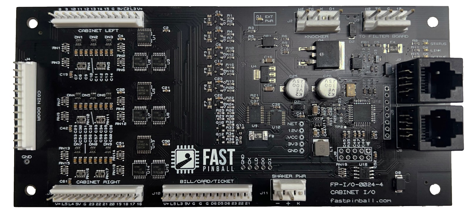
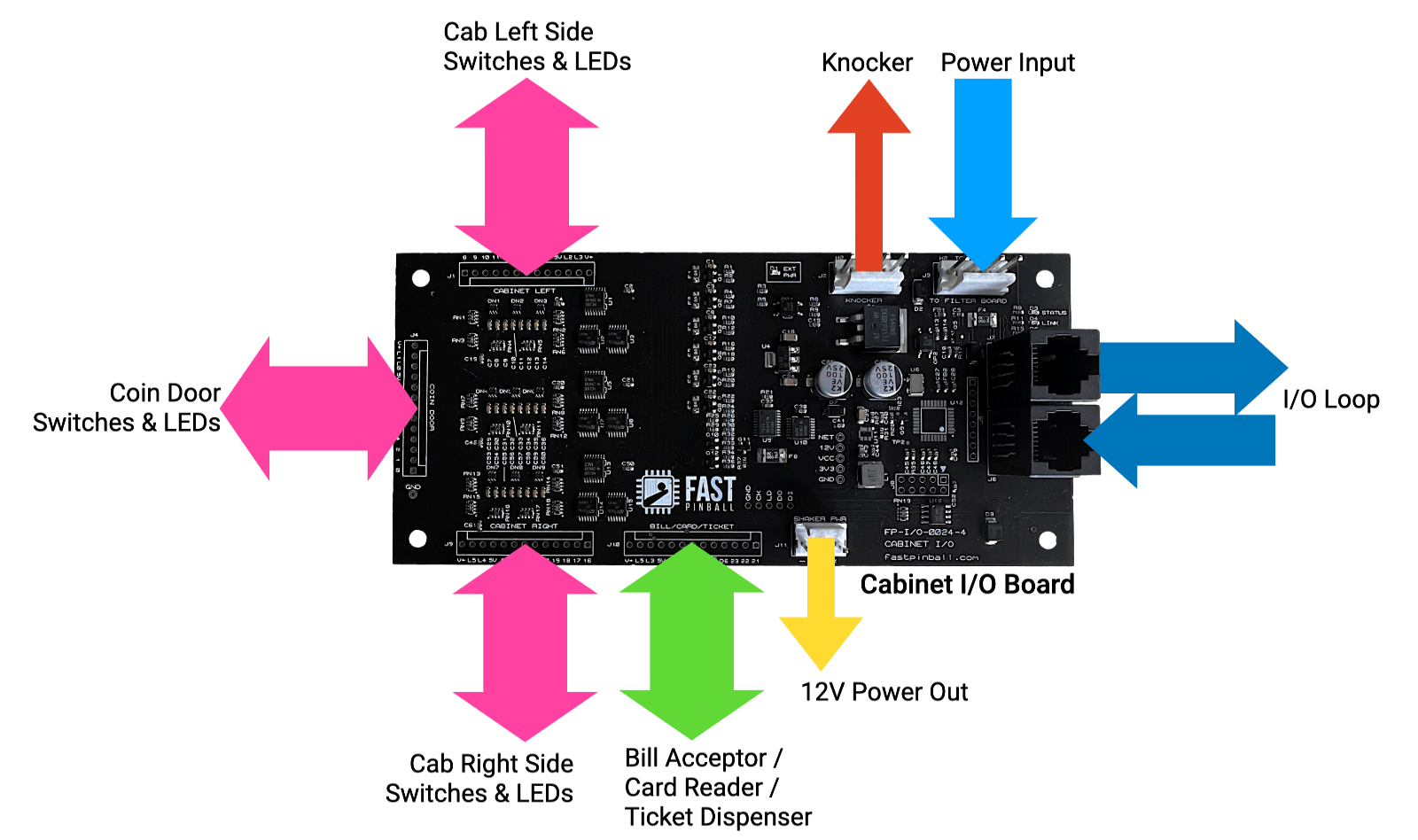
The FAST Cabinet I/O Board is a special purpose I/O board designed for placement in the pinball cabinet itself. This board handles all cabinet switches (flipper buttons, start button, etc.), as well as the coin door interface, a bill validator or ticket reader, low current drivers for LEDs (for the coin door and lighted buttons), and a high-current driver for a knocker.
Since this Cabinet I/O Board is part of the "Gen 2" modern platform (for machines built with the FAST Neuron Controller), switch and driver pairs can be on different boards, so you can have your flipper buttons connected to this Cabinet I/O Board while the flipper coils and EOS switches are connected to a different I/O Board under the playfield.
The FAST Cabinet I/O Board has three switch headers (for the cabinet's left side switches & buttons, the right side ones, and coin door interfaces).
Note
The cabinet I/O board requires that your Neuron Controller is running firmware v2.13 or newer. This board is not compatible with Nano controllers.
Features
- 24 switch inputs, 8 driver outputs.
- Specialized 13-pin headers for cabinet left, cabinet right, coin door, and bill/card/ticket interfaces, with the correct mixes of switch inputs, low current drivers, digital outputs, and 12V and 5V power outputs.
- 1 standard high current driver (typically for a knocker, but could be whatever you want).
- 6 low current drivers for LEDs for lighted buttons, coin reject LEDs, etc.
- 2 digital outputs (both active low and active high) for controlling the enable signals for bill validators and card readers. (Note that some digital outputs and low current drivers are shared, there are 7 total available between the two types.)
Driver Outputs
The Cabinet I/O board has 8 drivers. These are distributed across the various four headers on the board. The drivers are:
L0-L5are normal drivers for LEDs or anything that requires a current-limited open drain. Returns can be 12V or 5V (both are provided on all four headers).D6is a digital driver, open drain, good for up to 200mA. This can drive the ground side of a 12V or 5V referenced signal. The digital driver outputs are typically used for bill validator or ticket enable control lines, though they could drive other logic circuits too.D5andD6are TTL outputs. They must be referenced to 0 or 5V and can drive up to 20mA. Note thatD5andL5share the same driver control line, so you can use one or the other.D1on headerJ2for the knocker or other high current device is a standard high current driver just like any other driver on a standard FAST playfield I/O board.
The high current driver software number is 7
Even though the high current driver is labeled D1 on the board. In the software order, it's driver 7. (The various low current drivers are 0-6.)
Connectors Housings Needed
| Qty | Pins | Size | Description |
|---|---|---|---|
| 4 | 13-pin | 0.100" | switches / low current drivers |
| 1 | 3-pin | 0.156" | 12V power out |
| 2 | 4-pin | 0.156" | power in / knocker |
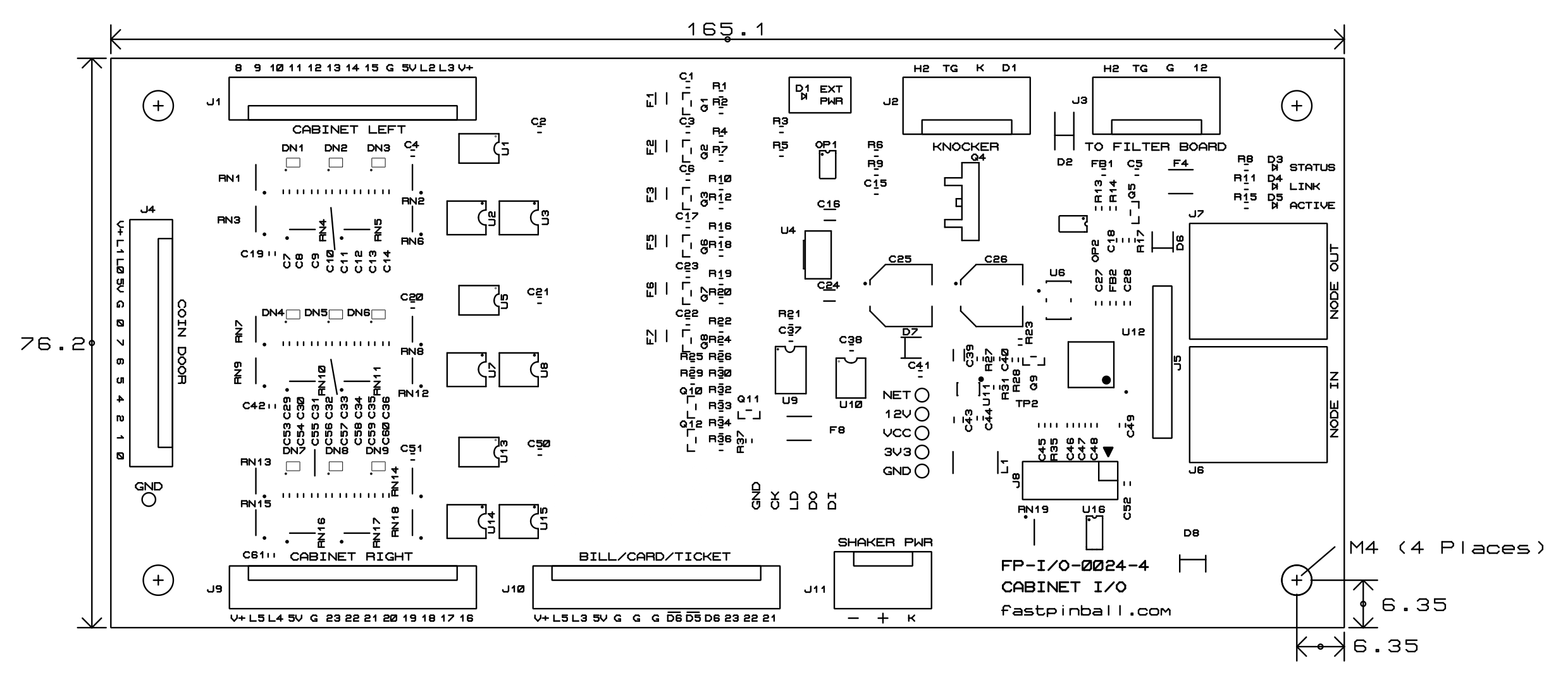
Mechanical Diagram
Dimensions are in mm
Status LEDs
There are 3 status LEDs on this board.
- STATUS is the processor status on this board. Slow flashing means everything is fine. Fast flashing means the board is inactive, which could include a watchdog timeout.
- LINK is on solid if this board can see its neighbor over the I/O loop and that everything is good. If this is off, then communication is not happening, which could mean there's a problem with the board, or the cable is bad or loose, or the neighboring board it's plugged into is bad.
- ACTIVE turns on (typically briefly) when a driver is currently active (e.g. it's actively firing) or a switch just changed state. This is great for testing. If a driver should fire and it doesn't, you can check to see if this LED flashes when the driver is supposed to fire. If yes, then you have a driver problem, if not, then it's a code or problem with the control system. You can also use this as a "local" switch test, as this LED should flash briefly when you activate a switch.
MOSFET / driver mapping
Since there is only one high current driver output on this board, there's only one MOSFET, Q4. Pretty easy! The replacement part number is IRL540NSTRLPBF, the same as the other FAST I/O boards.
Firmware Updates
FAST I/O Boards have microprocessors on them, which means they have firmware. Check our firmware page to see the latest versions and learn how to update your boards if needed.
Wiring Guides
Cabinet I/O Board Wiring Guide
Connector Pinouts
| J1 | PIN | CABINET LEFT | 1×13-Pin .100″ |
|---|---|---|---|
| 8 | Switch 8 | INPUT | |
| 9 | Switch 9 | INPUT | |
| 10 | Switch 10 | INPUT | |
| 11 | Switch 11 | INPUT | |
| 12 | Switch 12 | INPUT | |
| 13 | Switch 13 | INPUT | |
| 14 | Switch 14 | INPUT | |
| 15 | Switch 15 | INPUT | |
| G | Switch Return Ground | OUTPUT | |
| 5V | 5V always on | OUTPUT | |
| L2 | Low current driver 2 | OUTPUT | |
| L3 | Low current driver 3 | OUTPUT | Shared w/ J10 pin 11 |
| V+ | 12V always on | OUTPUT |
| J2 | PIN | KNOCKER | 1x4-Pin 0.156" |
|---|---|---|---|
| D1 | Driver 1 | OUTPUT | |
| K | KEY | N/A | |
| TG | Toxic Ground | OUTPUT | |
| H2 | 48V H2 circuit | OUTPUT |
| J3 | PIN | TO FILTER BOARD | 1x4-Pin 0.156" |
|---|---|---|---|
| 12 | 12V | INPUT | |
| G | 12V Ground | INPUT | |
| TG | Toxic Ground | INPUT | |
| H2 | 48V H2 circuit | INPUT |
| J4 | PIN | COIN DOOR | 1×13-Pin .100″ |
|---|---|---|---|
| 0 | Switch 0 | INPUT | |
| 1 | Switch 1 | INPUT | |
| 2 | Switch 2 | INPUT | |
| 3 | Switch 3 | INPUT | |
| 4 | Switch 4 | INPUT | |
| 5 | Switch 5 | INPUT | |
| 6 | Switch 6 | INPUT | |
| 7 | Switch 7 | INPUT | |
| G | Switch Return Ground | OUTPUT | |
| 5V | 5V always on | OUTPUT | |
| L0 | Low current driver 0 | OUTPUT | |
| L1 | Low current driver 1 | OUTPUT | |
| V+ | 12V always on | OUTPUT |
Coin Door switch labels may be misprinted
Some revisions of the Cabinet I/O board have a labeling error for the coin door header J4 where the switch inputs were labeled 0-7-6-5-4-2-1-0 instead of 7-6-5-4-3-2-1-0. If you have one of those boards, just ignore the labels as the pins and electronics are correct.
| J6 | WIRE | NODE IN | RJ45 – CAT5e/CAT6 |
|---|---|---|---|
| 1 | COM ENABLE | INPUT | |
| 2 | GROUND | GROUND | |
| 3 | Fused 12v | OUTPUT | |
| 4 | COM- | INPUT | |
| 5 | COM+ | INPUT | |
| 6 | Fused 12v | OUTPUT | |
| 7 | GROUND | GROUND | |
| 8 | GROUND | GROUND |
| J7 | NODE OUT | RJ45 – CAT5e/CAT6 | |
|---|---|---|---|
| 1 | COM ENABLE | OUTPUT | |
| 2 | GROUND | GROUND | |
| 3 | Fused 12v | OUTPUT | |
| 4 | COM- | OUTPUT | |
| 5 | COM+ | OUTPUT | |
| 6 | Fused 12v | OUTPUT | |
| 7 | GROUND | GROUND | |
| 8 | GROUND | GROUND |
| J9 | PIN | CABINET RIGHT | 1×13-Pin .100″ |
|---|---|---|---|
| 16 | Switch 16 | INPUT | |
| 17 | Switch 17 | INPUT | |
| 18 | Switch 18 | INPUT | |
| 19 | Switch 19 | INPUT | |
| 20 | Switch 20 | INPUT | |
| 21 | Switch 21 | INPUT | Shared w/ J10 pin 1 |
| 22 | Switch 22 | INPUT | Shared w/ J10 pin 2 |
| 23 | Switch 23 | INPUT | Shared w/ J10 pin 3 |
| G | Switch Return Ground | OUTPUT | |
| 5V | 5V always on | OUTPUT | |
| L4 | Low current driver 4 | OUTPUT | |
| L5 | Low current driver 5 | OUTPUT | Shared w/ J10 "D5" and "L5" |
| V+ | 12V always on | OUTPUT |
J10 changed between board revs FP-I/O-0024-3 and FP-I/O-0024-4
Prior to the -4 revision of this board, J10 was 11 pins and had a different pinout. The -4 revision of this board changed J10 to 13 pins and added two additional ground pins. The function of the boards is the same, the additional pins are just for convenience.
| J10 | PIN | BILL/CARD/TICKET | 1×13-Pin .100″ |
|---|---|---|---|
| 21 | Switch 21 | INPUT | Shared w/ J9 pin 6 |
| 22 | Switch 22 | INPUT | Shared w/ J9 pin 7 |
| 23 | Switch 23 | INPUT | Shared w/ J9 pin 8 |
| D6 | Digital Driver 6 | OUTPUT | Shared with pin 6 |
| D5 | TTL Driver 5 | OUTPUT | Shared with pin 13 and J9 pin 12 |
| D6 | TTL Driver 6 | OUTPUT | Shared with pin 4 |
| G | Switch Return Ground | OUTPUT | |
| G | Switch Return Ground | OUTPUT | |
| G | Switch Return Ground | OUTPUT | |
| 5V | 5V always on | OUTPUT | |
| L3 | Low current driver 3 | OUTPUT | Shared w/ J1 pin 12 |
| L5 | Low current driver 5 | OUTPUT | Shared w/ pin 5 and J9 pin 12 |
| V+ | 12V always on | OUTPUT |
| J11 | PIN | SHAKER PWR | 1×3-Pin .156″ |
|---|---|---|---|
| K | KEY | N/A | |
| + | 12V out | OUTPUT | |
| - | Ground | OUTPUT |
N or > jump the next page, P or < for previous, search with S or ?