FAST Power Filter Board for Nano-controlled machines (Retired)
Part Number: FP-PWR-005
This product is retired
This product is designed for FAST Nano-controlled pinball machines. If you're building a Neuron-controlled machine, you want to use the Smart Power Filter Board instead.
The FAST Power Filter Board provides an elegant way to integrate switching power supplies into a pinball machine with a FAST Nano Controller. This board allows a physical switch to be wired to the coin door to kill the high voltage at the power filter board when the coin door is open. (This switch only disconnects the high voltage. The 5V and 12V lines still run so the FAST controller and boards stay powered on.) The power filter board also has a switch output which opens and closes when the high voltage is enabled and disabled. You can wire this switch into any IO board switch input to trigger your game code to display that "High power disabled" message when the coin door is opened.
If your coils are not working...
The "enable" switch output MUST be closed in order for this board to provide high voltage. If you are just setting up your board for testing, put a jumper (or use alligator clips, etc.) across Pin 1 and Pin 3 of J2 "ENA IN" to enable the high voltage outputs.
In addition to supporting the main high voltage ("HV", most likely 48V) power circuit and 12V and 5V, the FAST Power Filter board has two additional voltage circuits (labeled V1 and V2) for additional needs you may have.
V1 is enabled and disabled via the high voltage switch and also is wired into a large capacitor. If you have a need for 24V or something like that, you can use the HV line for that. If you do not have other high voltage needs, then you can use the V1 line as an additional 48V line, and then all three capacitors will be used together for that combined HV. To do this, simply wire your 48V input to both the two HV inputs and also to the V1 input. (So three incoming +48VDC input lines.)
V2 is intended for additional lower voltage needs and is always on. Most people use it for an additional 5V line since the FAST Power Filter Board power circuits are limited to 7A max, and it's possible to exceed 7A on your 5V line if you have a lot of LEDs. In that case, you can get a larger 5V power supply and split the 5V inputs across the 5V and V2 inputs, and then each 5V output could use 7A (or whatever limit your PSU has, just be sure that the combined 5V outputs and fuses are LESS than the total rated output of your power supply.)
See the wiring guides and documentation (linked below in the "additional wiring resources" section) for details on all these topics.
Features
- Sits in-between your power supplies and your machine.
- Supports five independent power circuits, up to 7A each.
- Acts as a ground tie point for all DC power grounds in your machine.
- Has a physical switch input to enable / disable high voltage outputs. (e.g. for the coin door switch)
- Has a switch output which represents the state of the high voltage enable switch (e.g. to let your game code know the door is open and high voltage has been disabled)
- All 5 power circuits are independently fused. All fuses are 6x30mm on this board. LEDs under each fuse quickly show lines that are active and have non-blown fuses.
- Three large capacitors are used to offset voltage drop on the high voltage circuits when used with high-current drivers like flippers, magnets, and large motors.
- Typical power circuits used include:
- 48V for coils, etc.
- 12V
- 5V
- Two additional power circuits can be used as needed.
- V1 is a high voltage circuit, can be used as an additional 48V or for an alternate (24V, or...?) high voltage as needed. (12V minimum)
- V2 is a low voltage circuit, most often used for an addition 12V or 5V in machines with a lot going on that need more than 7A from one of those voltages. (If this is 5V, the fuse status LED for this line will be dimmer than the rest, but that's expected and fine.)
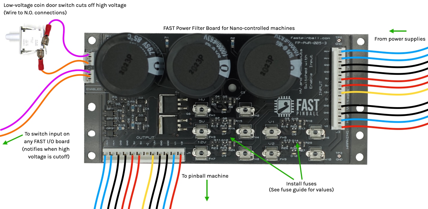
Connector Wiring
The following diagram is from the Power Filter Board Wiring guide, which is part of our series of step-by-step pinball machine wiring guides. See those guides for wiring details for this or any FAST Pinball board.
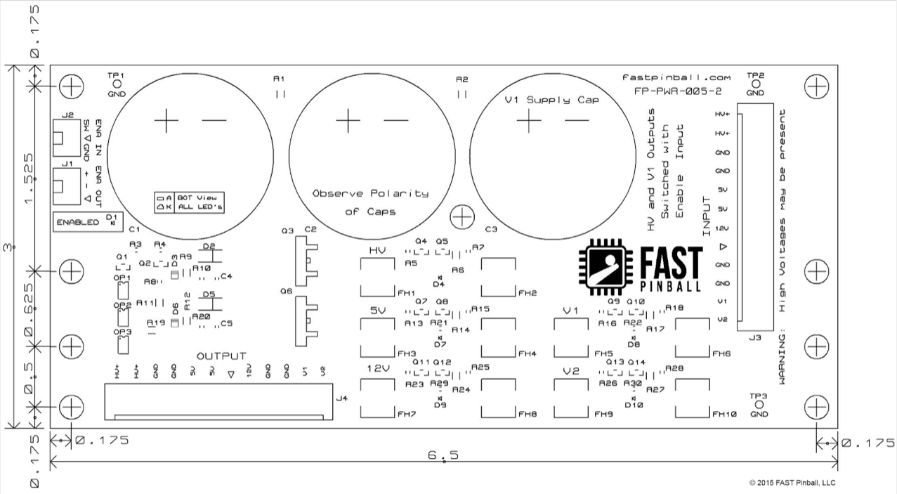
Mechanical Diagram
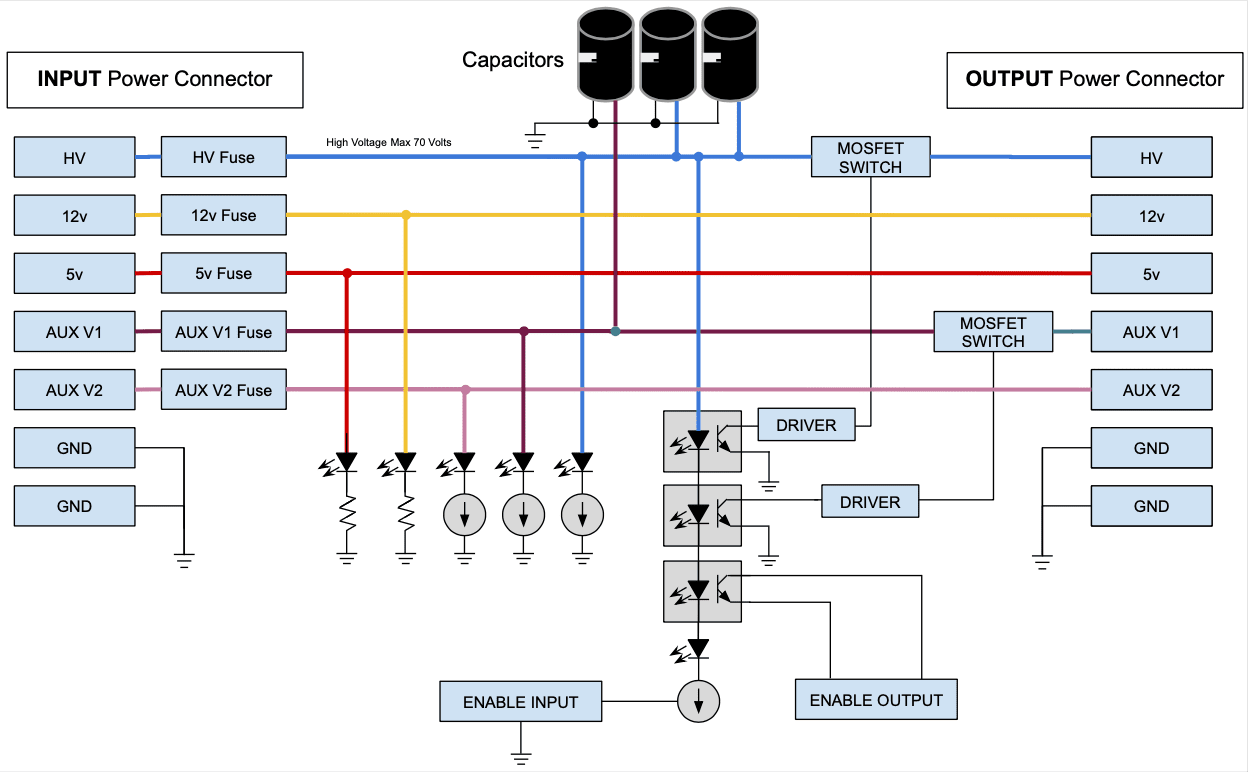
Block Diagram
Status LEDs
- ENABLED means the high voltage is enabled. If this LED is off, then your coils won't work and you will be sad. The high voltage is only enabled when a switch is closed across the "ENA IN" connector (J2). If you are just testing things, install a jumper or use alligator clips across pins 1 and 3 to close this connection and enable your board.
- 5 LEDs, one under each fuse, which light up green when the fuse is installed and working. (One for each fuse for each voltage.)
Connector Housings Needed
- Qty 2, 3-pin .156" Female Connectors
- Qty 2, 12-pin .156" Female Connectors
Connector Pinouts
| J1 | PIN | ENABLE OUT (Switch Input Triggered on Coin Door Open) | 3-Pin .100″ |
|---|---|---|---|
| + | Enable Out + | OUTPUT | |
| – | Switch Return | OUTPUT | |
| \/ | KEY | N/A |
| J2 | PIN | ENABLE IN (HV+ & V1 Enabled when Shorted) | 3-Pin .100″ |
|---|---|---|---|
| SW | Coin Door Switch Input | INPUT | |
| \/ | KEY | N/A | |
| GND | Coin Door Switch Return | INPUT |
| J3 | PIN | POWER INPUT | 12-Pin .156″ |
|---|---|---|---|
| HV+ | High Voltage (48V) | INPUT | |
| HV+ | High Voltage (48V) | INPUT | |
| GND | High Voltage Ground from Power Supply | INPUT | |
| GND | High Voltage Ground from Power Supply | INPUT | |
| 5v | 5 Volts | INPUT | |
| 5v | 5 Volts | INPUT | |
| 12v | 12 Volts | INPUT | |
| \/ | KEY | N/A | |
| GND | Ground from Power Supply | INPUT | |
| GND | Ground from Power Supply | INPUT | |
| V1 | Auxiliary Voltage 1 | INPUT | |
| V2 | Auxiliary Voltage 2 | INPUT |
| J4 | PIN | POWER OUTPUT | 12-Pin .156″ |
|---|---|---|---|
| HV+ | Fused High Voltage (48v) | OUTPUT | |
| HV+ | Fused High Voltage (48v) | OUTPUT | |
| GND | Power Return Ground | OUTPUT | |
| GND | Power Return Ground | OUTPUT | |
| 5v | Fused 5 Volts | OUTPUT | |
| 5v | Fused 5 Volts | OUTPUT | |
| \/ | KEY | N/A | |
| 12v | Fused 12 Volts | OUTPUT | |
| GND | Power Return Ground | OUTPUT | |
| GND | Power Return Ground | OUTPUT | |
| V1 | Fused Auxiliary Voltage 1 | OUTPUT | |
| V2 | Fused Auxiliary Voltage 2 | OUTPUT |
N or > jump the next page, P or < for previous, search with S or ?