How to wire the AC high voltage in your FAST Nano pinball machine cabinet
Wiring, high voltage, and electricity can be dangerous. Read this first!
The voltages and electricity discussed here can be dangerous and could cause property loss or death. It is your responsibility to ensure you are aware of these risks and comfortable with these processes. Furthermore your local jurisdiction may have regulations or rules which differ from what we discuss here, including wiring colors, standards, techniques, etc. Although based on broadly adopted methods, FAST Pinball does not employ Professional Engineers and this information is not professional recommendations. There may be errors, omissions, or typos here. Any pinball machine available to the general public should be reviewed by a licensed Professional Engineer in your region. Use this content at your own risk.
This guide is old (for FAST Nano-powered machines only)
This wiring guide is for pinball machines powered by a FAST Nano Controller. If you have a FAST Neuron Controller, please see the Neuron wiring guide.
This guide is the first in our step-by-step wiring series which shows you how to wire the AC high-voltage to your power supplies in a pinball machine powered by a FAST Nano Controller.
Before you read this guide, you should read these others first:
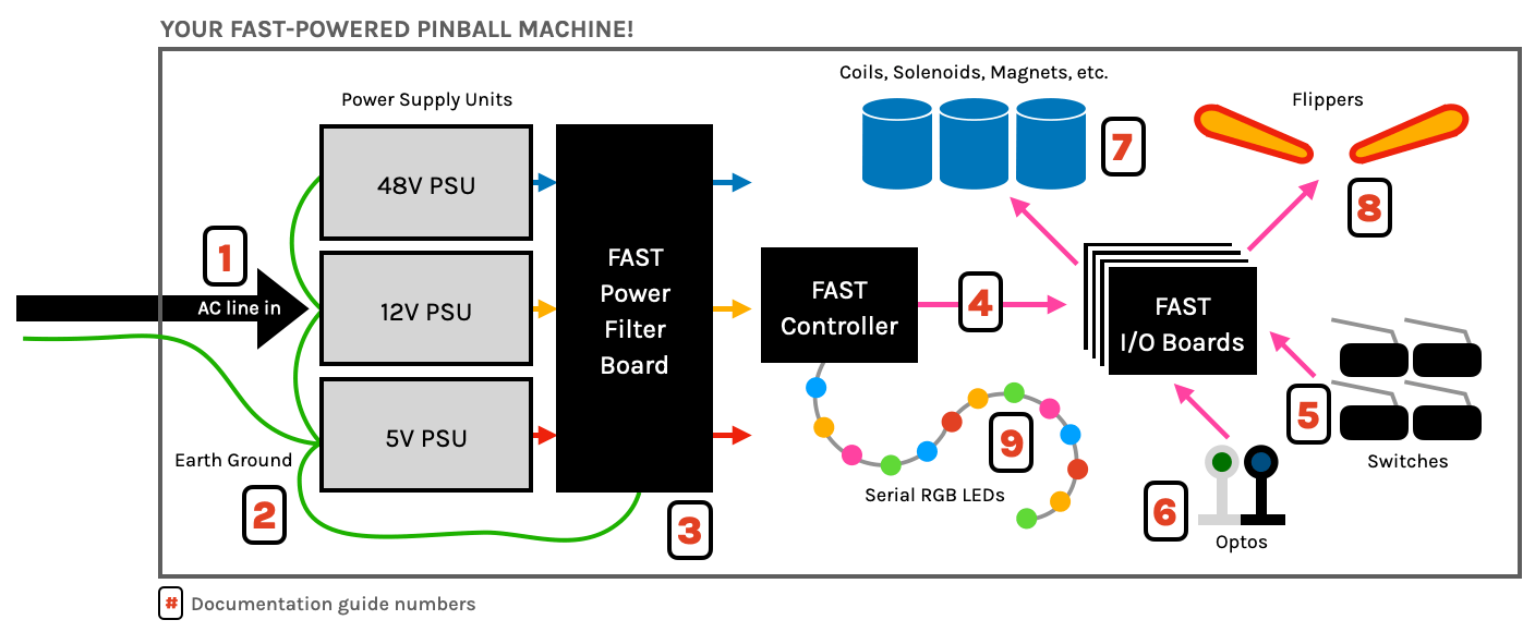
Let's use the following diagram to step through everything. (You can click to zoom in.) All the AC high voltage wiring should be 16 gauge.

IEC power cord socket + EMI filter
Starting from the back of the machine and working our way in, the first component is the socket that the power cord plugs in to. That hexagonal plug is called an "IEC" plug, and it has three pins for AC hot, neutral, and ground. For a pinball machine, we like the sockets that have EMI filters built-in. (You could also get a standalone socket and EMI filter, but that's just more steps.)
Main power switch
The main power switch is used to turn the machine on and off and functions by controlling the AC line from the wall to your power supplies.
Switch type
Next in line is the main power switch that will turn your machine on and off. In your pinball machine, you want to look for a switch that can support whatever your AC line voltage is (120V or 240V) and at least as much current as your line fuse (next section). When searching for switches, you'll easily find ones that support much more (250V/15A is common), which is fine.
You only need an SPST switch since you only need to connect the hot (black wire) from your IEC socket through your switch. (In some jurisdictions you might be required to switch both the hot and neutral lines.) Also if you feel more comfortable switching both hot and neutral, then you can get a DPST switch and go that route if you want. (Stern does this in their modern machines, even in the US.) But switching just the hot is how most appliances work and could be considered safer too since it keeps the neutral path always connected.
Switch location
In the old days, the main power switch was in the front underside of the cabinet, but new Sterns have the switch in the bottom of the backbox. So where should your switch be?
The challenge with putting the switch in the bottom front of the cabinet is that means you will have high-voltage AC in your cabinet, so you'll have to be extra careful to protect and insulate everything (wires, connections, switches, etc.) If your power supplies are going to be in your cabinet, then it probably makes sense for your power switch to be in there too.
The advantage of putting the switch in the backbox is that in that case, you would also put your power supplies and all AC high voltage components in your backbox. That way your cabinet doesn't have any high voltage in it, which is safer in general. (The 48V that runs the coils is not considered high voltage.) It's also easier to protect (with a metal box, cover, plastic, etc.) all your AC high voltage components if they are near each other (like in the backbox), versus having some power supplies in the rear of the cabinet and the power switch all the way in the front.
If you're intending on getting your machine certified (UL Listed, FCC, etc.) then the inspector is probably not going to love high-voltage running all over the place, which is why you're seeing companies like Stern isolate all the high voltage stuff to a small corner of the backbox which they can protect and isolate under a metal cover.
AC line fuse
It's also important that you have a fuse on the AC input side (hot wire) to protect the machine overall. As we wrote in our guide to fuses (which you definitely read, right? Seriously stop now and go and read that if you haven't yet), default values of 8A for 120V countries and 5A for 240V countries is probably fine.
If you're planning to get your machine certified, the AC line fuse must only be accessible from the inside of the machine. That's why we like the standalone fuse holders. If you are making a homebrew and don't care about certification, you can probably find a combo IEC socket / switch / fuse / EMI filter which is totally fine (and just as safe), but with the fuse accessible from the outside of the machine.
Fuse and switch: which order?
There's been some discussion around what's the "correct" order for the switch and fuse? Line in to fuse to switch? Or line in to switch to fuse? There are pros and cons to each, and again different jurisdictions and inspectors have different views on this. (Bottom line those is either is probably fine for your machine.)
The thinking for putting the switch first is that way when the switch is off, everything is off, and you don't have to worry about trying not to touch a fuse piece since everything is off. On the other hand, people could argue that the fuse should be first so that if it blows, everything is now unpowered, which should also include the switch. Again it probably doesn't matter. In our drawings we do AC line, then switch, then fuse.
Connecting power supplies
Now that you have filtered, switched, and fused AC coming in, the next step is to connect it to your power supplies. (We often use the acronym PSU, which technically means "power supply unit".)
Power supplies are pretty straightforward. They have three AC input connections, typically labeled "L" (line, or hot), "N" (neutral), and "G" or the ground symbol for AC ground. Then they have DC outputs, which is just positive (usually labeled something like "+V) and negative (labeled "-V" or "C" or "COM" for common). So your AC wires go in one side, and your DC wires come out the other side.
You will almost certainly have more than one power supply. You'll probably have three voltages: 48V, 12V, and 5V. We recommend a 48V supply and also a combo 5V/12V supply. (That combo supply has two sets of DC outputs, one for 5V and one for 12V). Depending on your needs, you might have three PSUs (for example, you might have a lot of LEDs and need more 5V power (higher amps) than our standard combo one can supply).
Connecting the AC side of your PSUs is as simple as connecting your three AC input lines (hot, neutral, and ground) to the three AC input terminals on each power supply.
Measuring power supply voltage
If you measure the DC output voltage of your power supply, you might find that it's not accurate and cannot be adjusted to an accurate range when the PSU is not loaded. (e.g. when there's nothing connected to it.) This is expected, as the voltage regulators in many switching power supplies need a load to get the voltage dialed in. So don't be surprised if you see something like 6+ volts on your 5V output, 13+ on your 12V, and over 50V from the 48V DC output with no load.
Once you connect your supply to your power filter board and through all the connectors, that will provide enough load. When checking voltages, measure from the output side of the filter board or your DC voltage distribution terminals so you can see the voltage that's actually being delivered to your machine. Measuring at the PSU output doesn't really tell you anything.
The 5V power is the most critical, as many 5V devices (like LEDs) will be damaged around 5.5V. You'd like to see the 5V somewhere between 5.0 and 5.2 or so. 12V can be a bit higher, even 13V is probably fine for most things, and the 48V really can be 50 or 52 even and you'll be fine. Technically the FAST I/O boards can handle more than that, but the 50-60V range is where the regulations in many locations change as those voltage levels become classified as "high voltage" which has stricter safety regulations, so aiming to keep the 48V in the 48-50ish range is probably best.
You must use crimped connectors
An important thing to know is that you should not connect your bare stranded wire to the screw terminal of the PSU (or to any screw terminal, for that matter). Instead, use some type of connector which is crimped to the end of your wire. (See our guide to crimping if you're new to this.) The reason you need to use a connector is to ensure that a stray copper strand doesn't touch a neighboring terminal and short out. Also it ensures a solid connection with low resistance.
The specific type of connector you use is a personal choice. You could use a fork connector (shown below), or a ferrule, or a ring connector, or probably others.

Some people choose to use ring connectors thinking the ring will prevent the wires from coming off if the screw comes loose. Just be aware that many screw terminals are designed where the screws don't fully come out, making ring connectors annoying in those cases.
Some people have asked if it's ok to "tin" the wires (to ensure stray strands don't come out) and then screw the bare tinned wires into the screw terminals rather than using crimped-on connectors. This is not recommended, as the solder on the tinned wire essentially freezes the wire into a circle shape, meaning the connector crimp can't mash it down, resulting in less conductive surface area contact which results in higher resistance.
Connecting multiple power supplies
If you have 2-3 power supplies, you'll have to figure out how to get them all connected to the hot, neutral, and ground lines from your AC line in. The diagram at the top of this guide shows a daisy-chain connection from the first PSU to the second. (Just note that each wire has its own fork connector crimped to it, with two connectors attached to each screw terminal. This is totally fine.)
Some people don't like this idea and instead prefer to run each of the three AC lines (hot, neutral, and ground) to their own breakout terminal connectors, and then run dedicated branch lines to each PSU. That's fine too. Here's a drawing showing how this would look with lever wire connectors. You could also use screw terminal barrier strips or some other approved method for connecting multiple high voltage wires inside of appliances.

Wire gauges
We discussed wire gauges in our guide to wire types, sizing, and colors, which you definitely read already, right? So you know AC wiring should be 16 gauge. We talked about fuses and fuse values in our guide to fuses. But it's worth circling back here just to check and make sure the wire you're using is appropriate for the AC high voltage side of your pinball machine.
First, to reiterate, it's important that you use stranded wire. Sure, the wire in your walls is solid copper, but solid copper is more brittle than stranded. This is fine in your walls since your house doesn't move, but a pinball machine will be kicked, pushed, shipped, moved, thrown on its back, shipped in cars and trucks, etc. Use stranded wire.
Next you need to figure out what the maximum current will be required over those wires and make sure the wire you select is rated high enough for it. To figure out the max current you'll need, you can look at your power supplies and add up the total amps they require (on the AC input side), keeping in mind that amps and volts are related so you need to make sure you're looking at the input amps for the line voltage of where you live.
Even if your PSUs could in theory draw more amps than your wire can support, you solve this by selecting a fuse value that protects your wiring. (Remembering the the slow blow fuses used in a pinball machine will allow more current than they're rated for, so if you have wire which can support 10A then you probably want to put an 8A line fuse in.)
This guide is part of our complete series on wiring your FAST Nano-controlled pinball machine. Click to see the rest!
Wiring guides for FAST Nano-controlled pinball machines
We have many guides and a complete wiring walk-through for your entire pinball machine powered by a FAST Nano Controller. Please read and understand all of the wiring guides before you start planning and physically wiring your machine.
Baseline wiring skills & knowledge
Important wiring and electrical background information you need to know before you start planning your machine's wiring.
FAST Nano-controlled Pinball machine wiring guides
The guides below walk you through a complete machine wiring, section-by-section. The numbers in the drawing match up to the numbers in each diagram. We assume you follow these in order. Click the image to zoom in.
N or > jump the next page, P or < for previous, search with S or ?