Troubleshooting FAST Pinball FP-EXP-0081
This guide will help you troubleshoot the FAST Pinball FP-EXP-0081 expansion board.
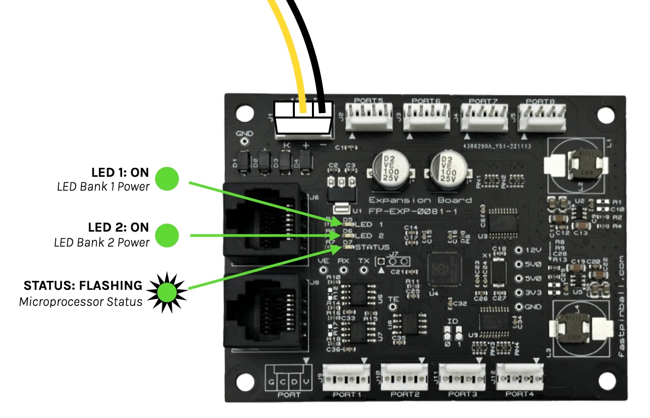
1. Connect 12V power & verify LEDs
The first step is to completely isolate the expansion board in question and verify it's behaving as expected. To do this, remove all connections from the board and let it fully power down. Then, attach only the 12V power. That's it. (If you get the 12V power from the Neuron, that's fine,)
Even with nothing connected, when the FP-EXP-0081 is powered on, you should see the LEDs light up. LED 1 and LED 2 should be solid green. They represent the voltage for the two banks of LED connectors. The STATUS LED should be flashing green, which means the board is up and running:
2. Verify voltage at the test points
If the status LEDs on your board are lit as you expect, the next step is to use the test points with your multimeter to verify the board is properly generating the various voltages it needs to operate. Touch your black test lead to the GND test point, and your red lead to each of the four test points labeled 12V, 5V0, 5V0, and 3V3. You should see the following around 12.0, 5.0, 5.0, and 3.3 volts for each.
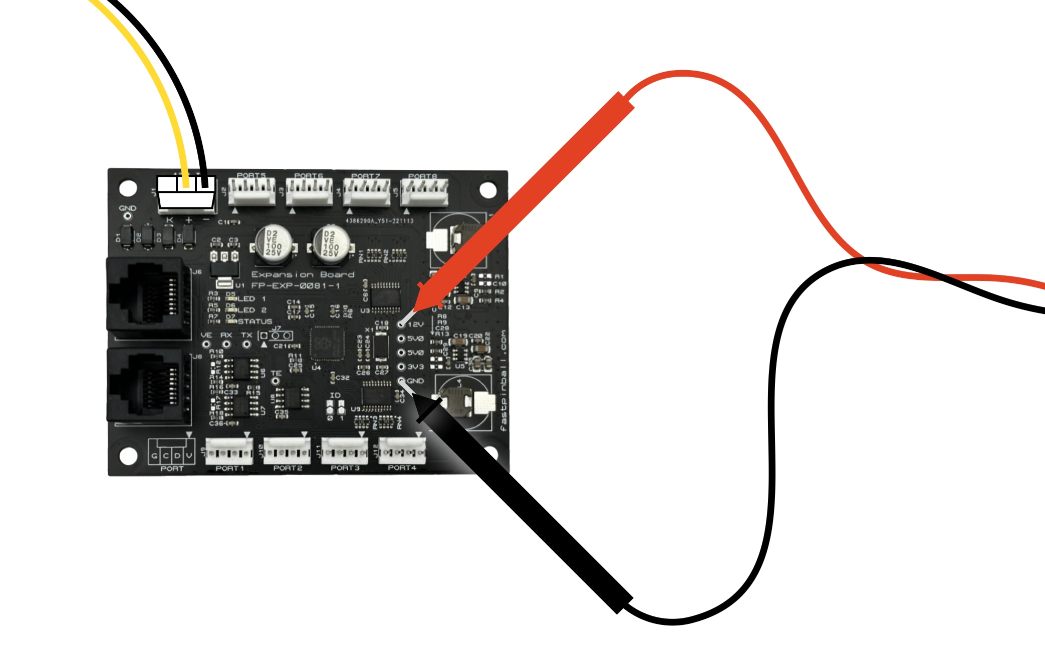
You can also use your test leads to verify you have 5V at each of the 8 LED ports. Touch the red lead to Pin 1 (the one with the triangle pointing toward it), and the black lead to the other end, Pin 4. (There's a diagram on the lower left corner of the board.) You should see 5V at each of the 8 LED ports.
If you're not getting any voltage readings, use your test leads to verify you have 12V coming into J1 by checking the pins of the wire connector powering your board.
3. Connect the Neuron
At this point, you've verified everything you can in isolation. The next step is to connect the expansion board to the Neuron controller via the a Cat-5 cable connecting the EXP bus.

Note that you can use either port on the expansion board, and either of the two EXP BUS ports on the Neuron. (But only use one cable to connect one port from each board, do not connect both to both.)
4. Connect via CoolTerm
The next step is to use a serial terminal over USB to connect to FP-EXP-0081 via Neuron.
If you've never done this, stop now and read the Neuron First Steps Guide which will walk you through connecting to the Neuron and using serial terminal emulator software.
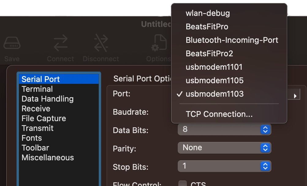
To troubleshoot the FP-EXP-0081 via the serial connection, you'll need to connect to the Neuron's EXP port, which is a different port than for the NET processor which was covered in the Neuron First Steps Guide.
The EXP port is the second port in the list of three ports that appear when you connect to the Neuron. Here's an example from CoolTerm on a Mac. (Note that the EXP port is the second numeric port which in this list is showing up in the third position. That Neuron First Steps Guide has more details on this and CoolTerm settings.)
When you connect, you might have a blank screen, or you might have some garbage characters, or you might have text which reads !BL2040:00 (The board's boot success message).
4a. Power cycle your hardware
Since we're troubleshooting together, ensure that everything on the EXP bus is reset by power cycling all the FAST boards. (Give them a few seconds while off to ensure they're fully reset.)
4b. Hit Enter four times
In order to clear out the connection, hit the Enter key 4 times. This will move the cursor down for each hit, but you shouldn't see any other characters on the screen. If you get an XX:F response, that means one of the boards was not in its fresh state, so power all the FAST hardware off (including the Neuron) and then back on and try again.
4c. Send an ID: Command
Next, type the following command id@84: Enter. You should get a response back that looks like this:
id@84:
ID:EXP FP-EXP-0081  0.8
If you get nothing back, then confirm that you typed the command correctly: i d @ 8 4 : Enter. ("ID" can be lowercase or uppercase.)
If you still get nothing back, ensure the Cat-5 cable from the EXP BUS port on the Neuron is connected to the one of the ports on the FP-EXP-0081. Even though there are two ports, only use one cable (either port on either board is fine). Do not connect both. You can also try swapping the cable or ports.
Also, the above command will only work for a FP-EXP-0081 expansion board. If you have a FP-EXP-0071 or FP-EXP-0091, then the command for you uses a different address.
4d. Turn on an RGB LED
If you have a WS2812 RGB LED handy (or a strip of them), you can them to one of the LED ports and then a command to turn it on.
ra@84:005500
That command will turn all LEDs on all ports to a medium green color. You can play with the command to change the color and brightness. For example, ra@84:ff0000 will turn them all to full brightness red. (There are other commands you can use when playing around with LEDs. )
Next steps: test with MPF
If you're using MPF, we have a repo with ready-to-go MPF configs you can use to verify you have MPF installed correctly and that it can talk to your FAST hardware. Instructions for using those are here.
N or > jump the next page, P or < for previous, search with S or ?