How to wire your FAST Neuron Controller
Wiring, high voltage, and electricity can be dangerous. Read this first!
The voltages and electricity discussed here can be dangerous and could cause property loss or death. It is your responsibility to ensure you are aware of these risks and comfortable with these processes. Furthermore your local jurisdiction may have regulations or rules which differ from what we discuss here, including wiring colors, standards, techniques, etc. Although based on broadly adopted methods, FAST Pinball does not employ Professional Engineers and this information is not professional recommendations. There may be errors, omissions, or typos here. Any pinball machine available to the general public should be reviewed by a licensed Professional Engineer in your region. Use this content at your own risk.
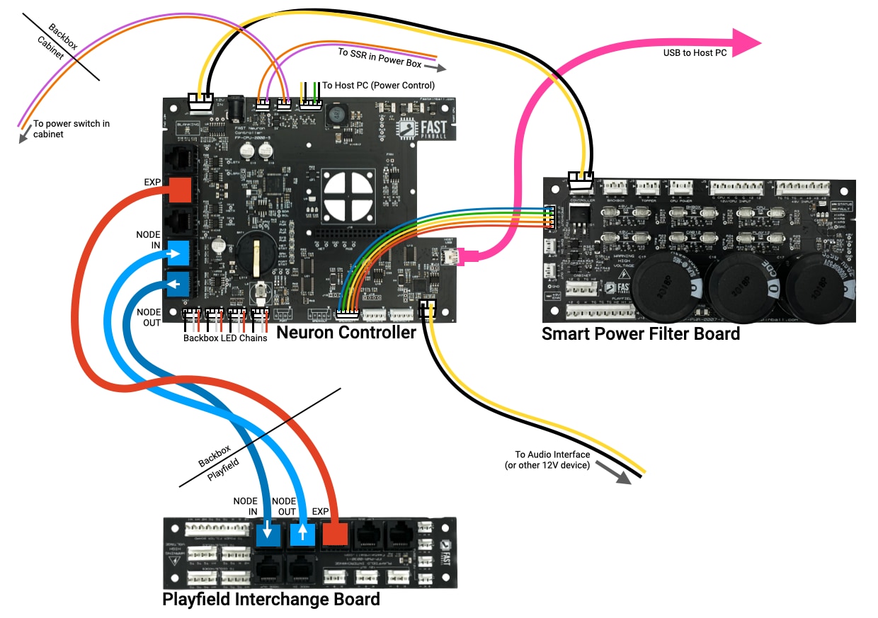
Continuing our series of wiring guides for Neuron-controlled pinball machines, let's look at how you wire up the actual Neuron Controller itself. The following diagram shows the typical wiring of a Neuron in your machine's backbox.

Neuron Location
The Neuron was designed to be installed in your machine's backbox. The main reason for this is that the Neuron will most likely be located nearby other machine electronics, like the host PC, audio interface, power filter board, SSR, and power supplies. If you put all those things in the bottom of your cabinet, especially with a homebrew project, there's a high likelihood that you'll drop a tool or screw or something into the electronics, and next time you turn it on, you'll end up with a pop and ULS (unexpected light show).
So if you decide to put the Neuron and related electronics in the cabinet, be sure to protect them with some kind of plastic cover to prevent this.
The other reason we like to keep the Neuron and other electronic guts in the backbox is that keeps the AC high voltage out of your cabinet, which is easier and safer to wire.
Neuron Header Connections
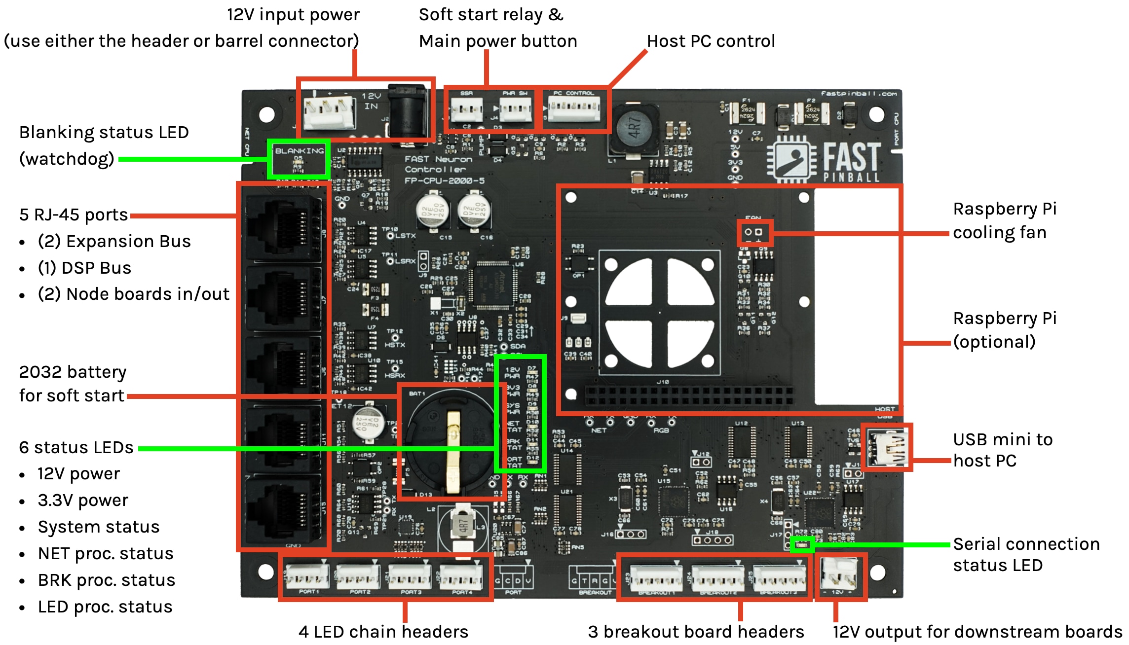
Many of the Neuron's connections have or will be covered in other guides, but let's walk through all the headers and what you need to know about wiring them. We'll use the same diagram from the Neuron product guide:

| Header | Description | Which guide has details |
|---|---|---|
J1 |
12V power input | Smart Power Filter Board wiring |
J3, J4 |
SSR relay & soft power switch | SSR relay wiring |
J5 |
Host PC control | Host PC wiring |
J10 |
Raspberry Pi connection | Raspberry Pi wiring |
J13 |
USB Host connection | Host PC wiring |
J26 |
12V power output | Fuses & current calculations |
J23, J24, J25 |
Breakout Headers | Expansion board wiring |
J19, J20, J21, J22 |
LED Chain Headers | LED wiring |
J15, J11 |
I/O Loop RJ-45 jacks | Playfield I/O board wiring |
J6 |
Display Bus RJ-45 jack | DMD wiring, Segment display wiring |
J7, J8 |
Expansion Bus RJ-45 jacks | Expansion board wiring |
BAT1 |
2032 Battery | SSR relay wiring |
N or > jump the next page, P or < for previous, search with S or ?