Wiring, high voltage, and electricity can be dangerous. Read this first!
The voltages and electricity discussed here can be dangerous and could cause property loss or death. It is your responsibility to ensure you are aware of these risks and comfortable with these processes. Furthermore your local jurisdiction may have regulations or rules which differ from what we discuss here, including wiring colors, standards, techniques, etc. Although based on broadly adopted methods, FAST Pinball does not employ Professional Engineers and this information is not professional recommendations. There may be errors, omissions, or typos here. Any pinball machine available to the general public should be reviewed by a licensed Professional Engineer in your region. Use this content at your own risk.
FAST Pinball Cookbook: Lower Third Wiring
This pinball cookbook recipe will show you how to wire up the lower third of your playfield, including flippers, slingshots, the trough, switches, and LEDs. It uses the FAST boards from the starter bundles, including the Neuron Controller, an I/O 3208, and an expansion board.
This recipe is a good way to get your feet wet with FAST Pinball wiring, and a fun way to learn how to wire a pinball machine. It will probably take you several evenings to complete.
The FAST Pinball Cookbook
This guide is a "recipe" from the FAST Pinball Cookbook. The cookbook shows you practical implementation of the knowledge and techniques covered in the wiring guides. It's important that you've read the wiring guides before attempting to follow one of the recipes from the pinball cookbook.
What is the lower third?
In pinball parlance, the term "lower third" is literally just the lower third of the playfield. It's special because it's almost identical in "standard" pinball machines today. (The particular layout of the standard lower third is called the "Italian Bottom".)
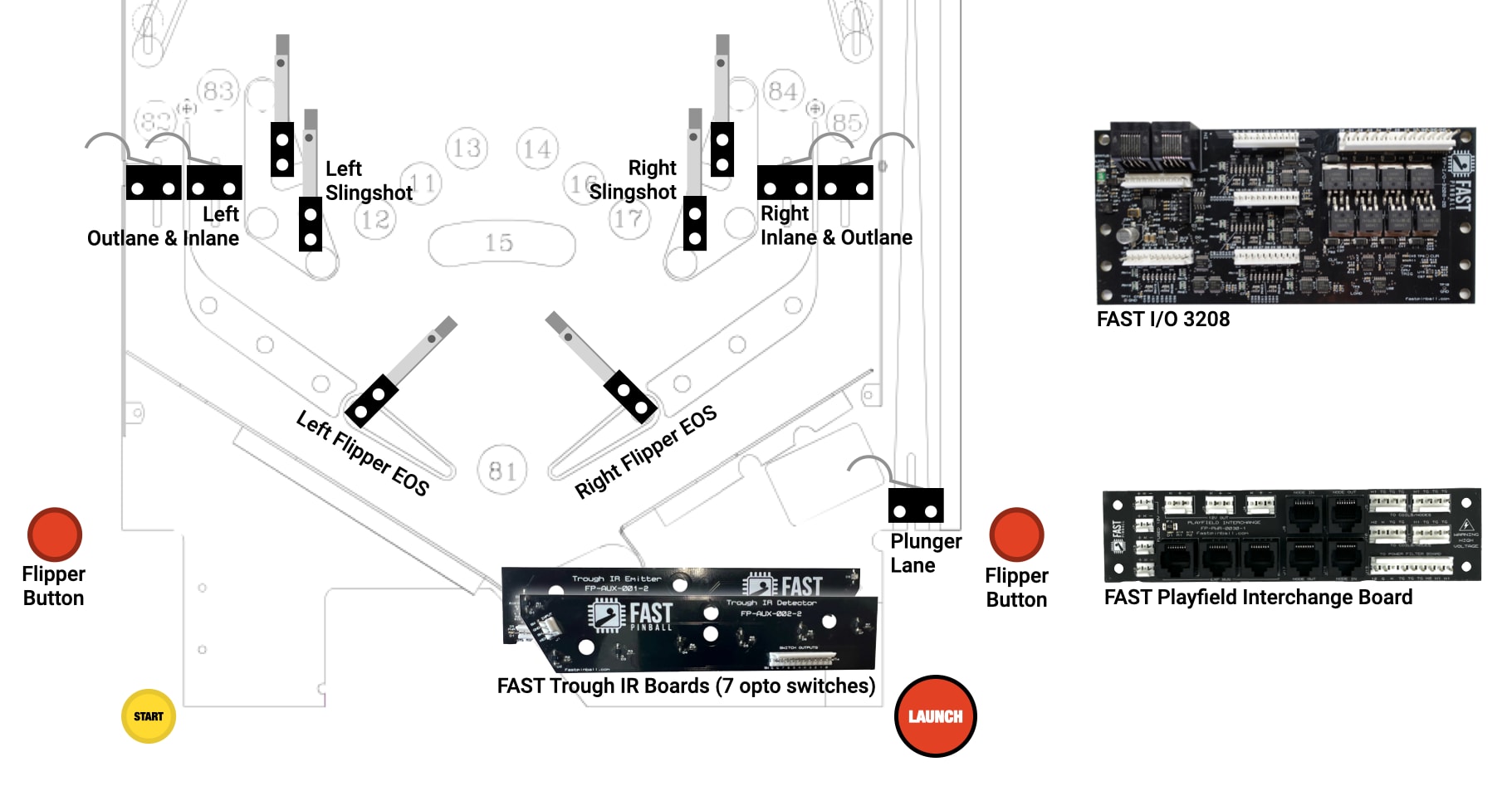
Here's an image of a typical Italian Bottom. (This is from Attack From Mars.)
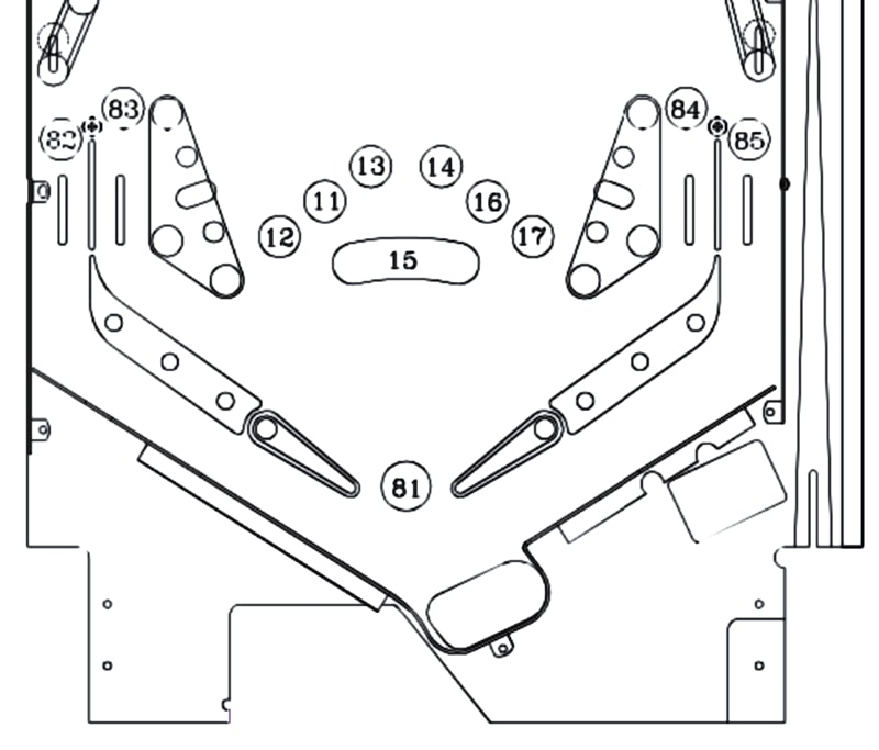
It's got two flippers, two slingshots, and one inlane and outlane on each side. There's a tough, a solenoid-fired plunger, and a plunger lane switch. On the bottom, there are all the FAST Pinball recommended best practices. There are EOS switches for the flippers, as well as dual-wound coils. The trough is a standard Williams 6-ball trough (with a jam opto).
Moving on to LEDs, this lower third is also very typical. We will be wiring RGB LEDs for the playfield inserts, and also RGB LEDs for the GI. (The GI is the general illumination, or the "backlight" of the playfield, and is handled via dome-shaped LEDs under the plastics that stick up through holes in the playfield.)
Prerequisites
Before you start actually building this recipe, it's important that:
- You have read the FAST Pinball wiring guides for all the components and mechs you're using.
- You know how to crimp pins and make wire harnesses.
Tools
Besides the tools you need to install and adjust the physical pinball mechs in the playfield, for this recipe you'll need:
- Wire strippers
- Wire crimpers
- Wire cutters
Your pinball project
This recipe is about wiring a lower third of a pinball playfield. So you'll obviously need that, and a few other things:
- A "lower third", with the pinball mechs installed. (This could be in a cabinet, on a rotisserie, or on a workbench.)
- A complete "power box"
- Wiring for the smart power filter board to playfield interchange board is complete.
FAST Pinball Components
- FAST Neuron Controller
- FAST I/O 3208
- FAST Expansion Board (either FP-EXP-0071 or FP-EXP-0081)
- FAST Playfield Interchange Board
- FAST Trough IR Emitter / Detector boards
- FAST RGB LEDs for playfield inserts
- FAST RGB LEDs for GI
Other parts
- Wire for everything (as covered in the pinball wiring standards guide).
- Connectors and crimp pins
Now let's jump in and start wiring! We'll start with the solenoids, then move on to the switches, and then the LEDs.
That order, by the way, is somewhat arbitrary. Most people just want to get flipping as quickly as possible. And you'll probably have a few iterations of your white wood before you even get to LEDs. The point is you can do the wiring in whatever order you want.
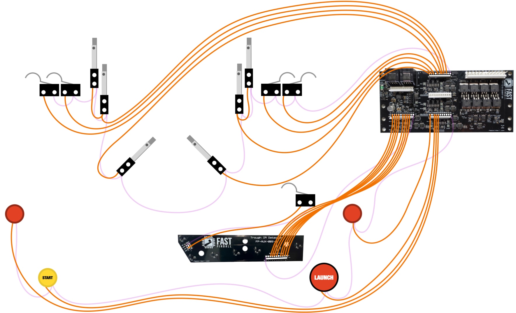
Lower third solenoid wiring
The following diagram shows the six solenoids in the lower third of a pinball machine. Since the flipper coils are dual-wound, they each count as two. Wiring the solenoids involves the FAST I/O 3208 and the FAST Playfield Interchange Board. (This recipe will not show the components behind these, such as the Neuron Controller, The I/O Loop wiring, the FAST Smart Power Filter Board, or the Power Box.)
Note the magnified views of the two header which will be used when wiring your solenoids. Each diagram will show this so you can see the labels of the pins.
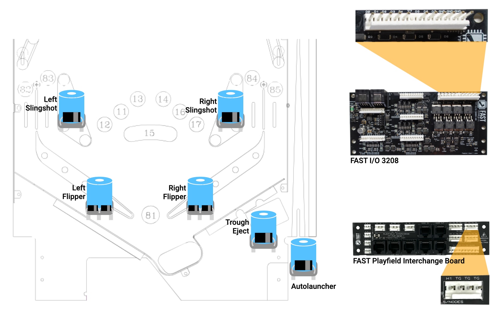
This chart shows the eight drivers outputs on the I/O 3208 that we'll use for each of the solenoids. How did we pick these? Somewhat arbitrary, really. It's based on which driver control on the I/O board is connected to which solenoid, and frankly the order we picked was the one that made for the simplest diagram. So feel free to follow this numbering order, but if it makes more sense in your scenario to swap some around, go for it!
| Driver | Description | I/O Loop Number (hex) |
|---|---|---|
| D0 | Plunger autolauncher | 0x00 |
| D1 | Trough eject | 0x01 |
| D2 | Left Flipper hold | 0x02 |
| D3 | Left Flipper power | 0x03 |
| D4 | Right Flipper hold | 0x04 |
| D5 | Right Flipper power | 0x05 |
| D6 | Right Slingshot | 0x06 |
| D7 | Left Slingshot | 0x07 |
The underlying knowledge for wiring solenoids is covered in the solenoid wiring guide, so refer back to that if the reasons for doing anything here doesn't make sense.
Toxic grounds
The first wires we'll run will be the toxic grounds from the I/O board back to one of the 48V playfield power headers on the interchange board. This is illustrated in the diagram below. (The black wires with pink fuzz are the toxic grounds.)

We are running 3 wires because that's what the formula from the wiring guide recommended. In our case, we have 2 high current coils (the power windings from the flippers), plus we need 1 more for everything else, so that's 3 total.
As for which header on the playfield interchange board to use, you can choose either of the three 48V #1 headers (J5, J6, or J11). J10 uses the secondary 48V circuit which you most likely would not use for standard lower third solenoids.
Run the 48V supply wire
Next, we'll run the 48V supply wire from the playfield interchange board to each of the solenoids. This will be a single run which is daisy chained from coil to coil, as illustrated in the diagram below.
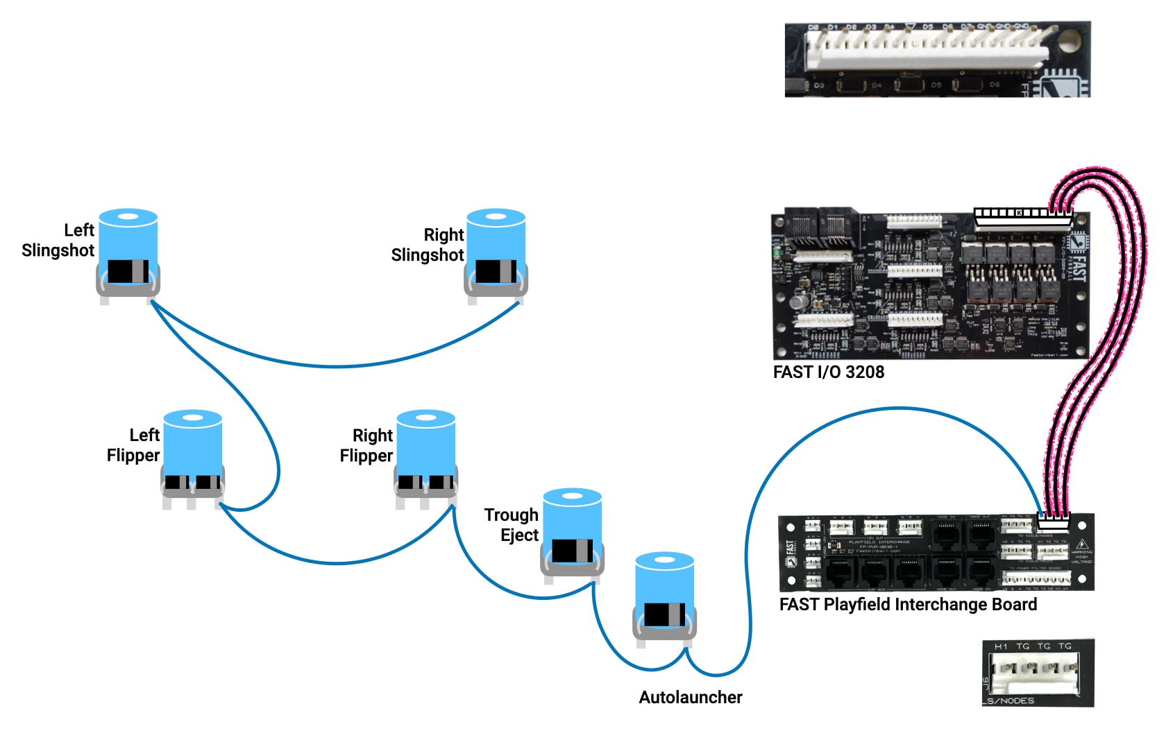
Remember, you MUST have diodes on your solenoids, and you MUST connect this blue 48V wire to the lug of the coil that is connected to the side of the diode with the stripe. ("Stripe points towards blue." Memorize that.)
You can attach the coils to this wire in any order. Since this is just 48V, it doesn't change any numbering or anything.
For the flipper coils, the 48V wire will go to the lug which is connected to both windings, so look closely and use the lug with two wires (one thick and one thin) connected to it.
It's ok to use a single wire for all 8 of these solenoids. Again, going back to the guidance in the solenoid wiring guide, a single blue 48V wire can support 2 high current drivers plus as many regular drivers as you want.
So with 1 48V wire and 3 toxic grounds, it makes sense to connect all 4 of these wires to the same 48V header on the interchange board. This way, each of the 48V headers can go to a different part of the playfield.
Run the driver control lines
The final step to get your solenoids working is to run the individual driver control lines from the I/O board to the solenoids. This is illustrated in the diagram below.
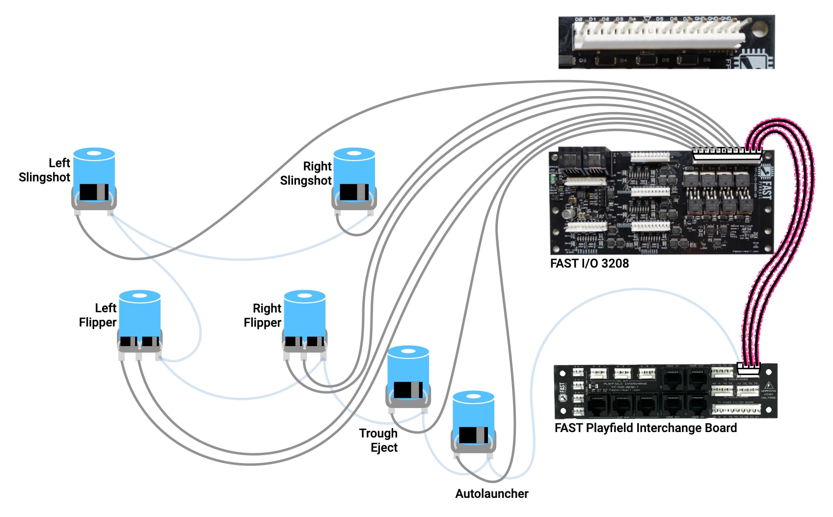
The driver control lines are the gray wires in the diagram. The exact pin each wire goes to on the I/O board is what affects which driver number that solenoid is. So feel free to follow the table above, or not.
For the flipper coil, look for the two lugs that only have one coil winding wire each connected to them. The one with the thick wire is the power winding, and the thin wire is the hold winding. (And again, the one with both is where the blue 48V wire should go.) Also your flipper coil should have two diodes on it.
All your wires are the same color? Seriously??
In the diagram above, you'll notice that all the solenoid control wires are gray. And in our pinball wiring standards guide, we recommend using white or gray for these wires. For our drawings and diagrams, we keep all the same types of wires the same color since it's easier to look at the drawing and quickly see what's going on.
But in the real world, you might not want all the wires to be the same color. (It's not the worst thing these days, since the wire bundles are smaller and only run back to a "local" I/O board. In the '90s when you had a 1-inch thick bundle of wires running back to the backbox, you needed all those colors and stripes!)
That said, if you want to use colors here, or striped wire, go for it! Just make sure you follow the pinball wiring standards for type and quality of wire. (And if you go with colors, don't use a color you have elsewhere in the machine. So skipping yellow, black, blue, orange, and purple, the leaves red, green, brown, pink, white, and gray. But for real, this is your machine, do what makes you happy!
Lower third switch wiring
Now that all your solenoids are wired, it's time to wire the switches. The standard lower third switches are illustrated in the diagram below. Also note the FAST Trough IR boards, which will be used for the opto switches in the trough.
Wow, a pinball italian bottom uses 20 switches! This is why we use an I/O 3208 board for the lower third. We will use 20 of the 32 switch inputs, which works out to 2 full headers of 8 plus another 4 switches on the 3rd header for cabinet buttons.
Here are the switch numbers we'll wire up today. Again, follow them, or not. It's up to you. Note the numbering gap, as the specific connectors that are most convenient work out to be the first 16 and then another batch of 4. (This is totally fine. There is no need to use switches in order. Any switch not connected will just never be activated.)
| Switch | Description | I/O Loop Number (hex) |
|---|---|---|
| 0 | Trough 1 | 0x00 |
| 1 | Trough 2 | 0x01 |
| 2 | Trough 3 | 0x02 |
| 3 | Trough 4 | 0x03 |
| 4 | Trough 5 | 0x04 |
| 5 | Trough 6 | 0x05 |
| 6 | Trough Jam | 0x06 |
| 7 | Plunger Lane | 0x07 |
| 8 | Right Flipper EOS switch | 0x08 |
| 9 | Right Slingshot (bonded pair) | 0x09 |
| 10 | Right Inlane | 0x0A |
| 11 | Right Outlane | 0x0B |
| 12 | Left Flipper EOS switch | 0x0C |
| 13 | Left Outlane | 0x0D |
| 14 | Left Inlane | 0x0E |
| 15 | Left Slingshot (bonded pair) | 0x0F |
| 24 | Right Flipper | 0x18 |
| 25 | Launch Button | 0x19 |
| 26 | Start Button | 0x1A |
| 27 | Left Flipper | 0x1B |
The "bonded pair" reference for the slingshots means that they are wired together in parallel, so either switch in the pair being activated will trigger the switch. This is a common technique for pinball slingshots and saves a switch input on each side.
The switch wiring techniques and knowledge needed for this recipe are covered in the switch wiring guide, if you want to go back and refresh yourself with that first.
Switch ground returns
The first thing to wire will be the common switch ground returns. Remember that the most important rule for wiring switches is that both legs of a switch must be connected to the same I/O board, but the specific header they connect to doesn't matter. So while we can wire all the switch ground returns to a single switch ground pin, it's much more practical to break it up. (You'll have different little bundles of wires going to different parts of the playfield, so that's why there are multiple switch ground pins. In your machine, you might end up using more or different combinations of wires here.)
Similar to the 48V wire, these purple switch grounds are just daisy chained from switch to switch. Just solder two wires to the same lug. Mechanical switches do not have polarity, and they should not have diodes attached.
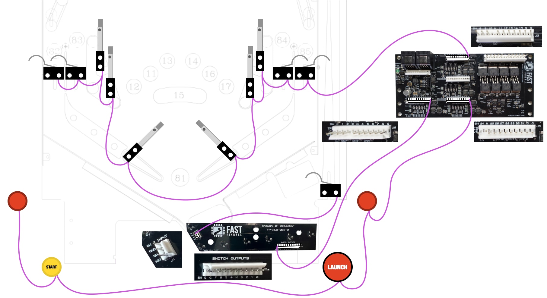
Trough IR receiver board
For the trough IR receiver board, you'll notice that it has a full 11-pin, 0.100" header which exactly matches the switch header on a FAST playfield I/O board. So you can just make a wiring harness with 11-pin connectors on both ends, and plug it into the I/O board and the IR receiver board. (If you do this, you don't need both switch grounds here.)
The trough has 7 optos: 6 for the six balls, and one in the jam location. So that means there's one "extra" switch, which is what that little header J1 labeled SW 7 INPUT is for. We designed it to run over to your plunger lane switch. (In your actual machine, this trough IR board is flipped around so that header is near the plunger lane.) So those eight switches are easy!
Cabinet buttons
This recipe shows connecting your 4 cabinet buttons (flippers, start, and launch) to the same playfield I/O 3208 board. This is fine, but not ideal since it means you'll have to have a long run of switch wires running from your playfield I/O board to the back of the playfield, into the cabinet, and then to the front of the machine for the buttons.
Many people instead choose to put an I/O board in the cabinet, an we have a cabinet I/O board specifically designed for this case. (It's similar to the playfield I/O boards, but it also supports the various coin door interfaces, LEDs in lighted buttons, and a knocker.) In the meantime, you can wire your cabinet switches to any I/O board.
If you have experience wiring FAST Nano-controlled pinball machines, you might recall some limitations around keeping switches and their related drivers plugged into the same I/O board. This limitation no longer applies in Neuron-controlled machines, so if you have your flipper buttons connected to an I/O board in your cabinet, and your flippers and EOS switches connected to a playfield I/O board, that's fine. Any switch, any driver, any I/O board, all good!
Switch inputs
Once your common switch return wire is run, you can run the individual switch lines back to the switch inputs on the I/O board. This is all the orange wires below. (And again, all our wires are orange because it makes the diagram easy to understand. If you want to use individual colors in your machine, go for it!)
We'll use one full header, J9 for switches 0-7 which will connect straight to the trough board for its 8. Also don't forget to connect the other wire from the plunger lane switch to the SW 7 INPUT header on the trough IR board.
The lower third playfield switches will connect to header J3 and be switches 8-15. If you count the actual number of switches in the lower third, you'll see there are 10, but we are putting them into a switch header for 8. What gives?
In this case, remember that the each slingshot has two leaf switches, but that those switches are wired in parallel so they are effectively seen as one switch. Note that for those switches, the orange switch input line is daisy chained from one slingshot switch to the other.
For the cabinet switches, again, pretty straightforward, just run the wires to the switch inputs on the I/O board. We chose the fourth header on the 3208 to make them switches 24-27.
Trough IR Emitter 12V
There's one more switch-related thing to connect, and that's to supply the power to the other trough board, the one that has the IR LEDs which shine through the trough to the detector board. That power comes from one of the low current 12V outputs on the playfield interchange board.
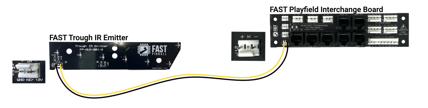
Details of this are covered in the opto wiring guide.
By this point, all your flippers and solenoids are wired, and you should be able to create a basic FAST Serial Protocol configuration script, or an Mission Pinball Framework configuration, to actually flip and play your machine!
Wiring lower third LEDs
While you don't need LEDs on your early white woods or test playfields, wiring them up is also fairly straightforward once you have a more final playfield. This diagram shows what you're going for.
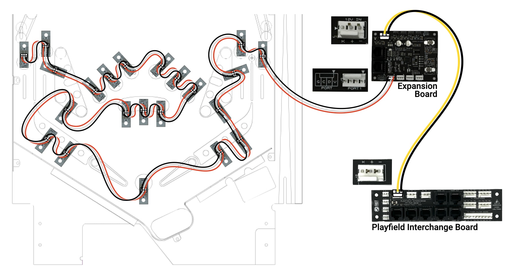
This guide assumes you're using WS2812-compatible LEDs, which are RGB and run at 5V. (The 5V power for the LED chains is generated on the board from the 12V power source.) The expansion board receives 12V high current power from the playfield interchange board, which you can wire now.
The chains of LEDs are connected to one of the LED ports on the expansion board. Each port has 4 pins, as they're designed to also support APA-102 style LEDs which use 4 wires. The WS2812 LEDs only use 3 wires, so you only need 5V, ground, and a data line. These are labeled V, G, and D on the expansion board LED port. The C is for "clock" and not used for WS2812 LEDs.
Each LED has an "in" and "out" direction, indicated by the arrow on the LED board. The 5V and ground wires are not directional, since they're just providing power. But the data connection is directional, and the data line from the expansion board is connected to the "in" side of the first LED in the chain. The "out" side of the that LED is connected to the "in" side of the next LED in the chain, and so on. Nothing special has to be done with the last LED in the chain, it just has an "out" side that is not connected to anything.
Chains of LEDs in FAST Neuron-controlled machines are limited to a maximum of 32 LEDs. This is due to the voltage drop which happens due to all the LEDs, wires, and connectors.
Wiring your lower third will involve both playfield insert LEDs and GI (through hole dome-style) LEDs. The inner guts of these two styles of LEDs are identical, and you can mix-and-match them as you wish within the same chain. You should design your chains based on whatever makes the physical wiring the easiest. You do not need chains dedicated to GI or playfield LEDs.
What a mess!
That's pretty much it! Wow, take a look at what you just built!
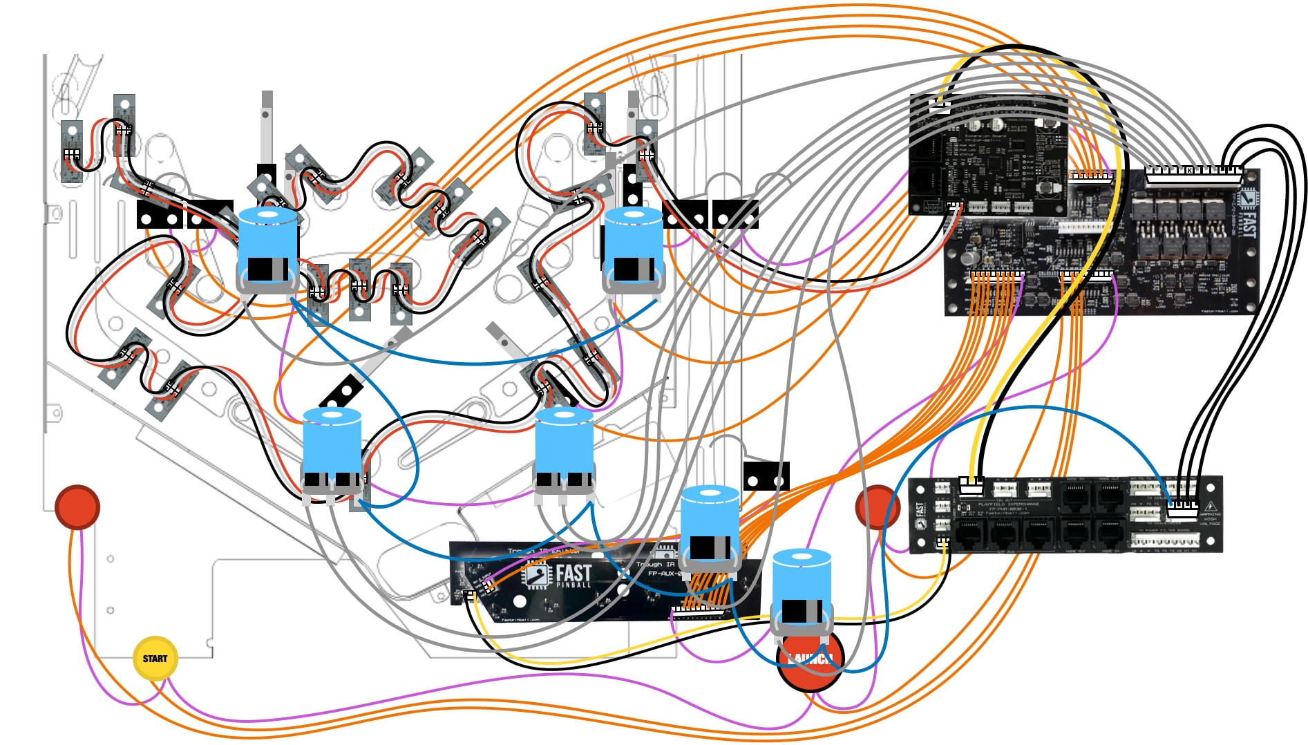
First, did you ever imagine that you could look at something so crazily complex and actually understand what everything does? You literally know what every wire does in that drawing!
Second, you'll see that playfield wiring management and organization is important. You will definitely mess this up when you wire your first playfield. (We all do!) As you get more experience, you'll start to get a feel for the order of wiring, how you bundle them, how you route them, etc. But chances are your first playfield will look something like the drawing above, which is fine.
You did it! Have fun playing your machine!
N or > jump the next page, P or < for previous, search with S or ?