Wiring the Cabinet I/O Board in a FAST Neuron-controlled pinball machine
Wiring, high voltage, and electricity can be dangerous. Read this first!
The voltages and electricity discussed here can be dangerous and could cause property loss or death. It is your responsibility to ensure you are aware of these risks and comfortable with these processes. Furthermore your local jurisdiction may have regulations or rules which differ from what we discuss here, including wiring colors, standards, techniques, etc. Although based on broadly adopted methods, FAST Pinball does not employ Professional Engineers and this information is not professional recommendations. There may be errors, omissions, or typos here. Any pinball machine available to the general public should be reviewed by a licensed Professional Engineer in your region. Use this content at your own risk.
This guide shows you how to wire the FAST Cabinet I/O board FP-I/O-0024 which is used for cabinet I/O, including the cabinet buttons, coin door, bill validator, ticket dispenser, knocker, shaker motor, and other devices in your pinball machine's cabinet.
The FAST Cabinet I/O board is conceptually similar to the playfield I/O boards we covered in a previous guide. (Read that guide first if you haven't yet.)
This guide is for the FP-I/O-0024 Cabinet I/O board
FAST Pinball has manufactured several Cabinet I/O boards for commercial partners over the years, and many look similar to this board. This guide is specifically for the FP-I/O-0024 Cabinet I/O board, and specs and pinouts will be slightly different from boards in the FP-CAB-xxx family.
You don't have to use the Cabinet I/O board for your cabinet I/O; a standard playfield I/O board is totally fine. But the Cabinet I/O board has several features that make it a better choice for cabinet I/O.
The FAST cabinet I/O board has several types of wiring connections:
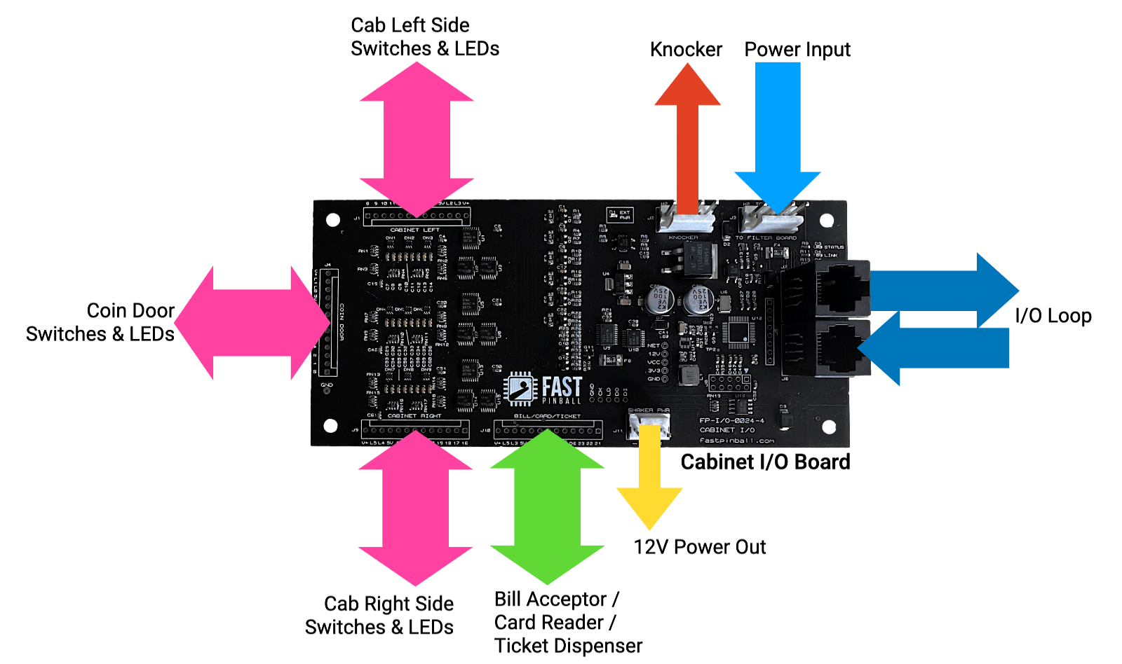
- FAST I/O Loop (Cat-5 Ethernet cables in/out, like all I/O boards)
- 48V and 12V power input (from the smart power filter board)
- Knocker coil driver (48V, driver control, toxic ground return)
- Cabinet Left & Cabinet Right headers (switch inputs, low current LED drivers)
- Coin Door header (switch inputs, low current LED drivers)
- Bill/Card/Ticket header (switch inputs, low current LED drivers, digital outputs)
- 12V high current power output (for a shaker motor, cabinet RGB LEDs, etc.)
Let's walk through the wiring for each of these in detail.
FAST I/O Loop wiring
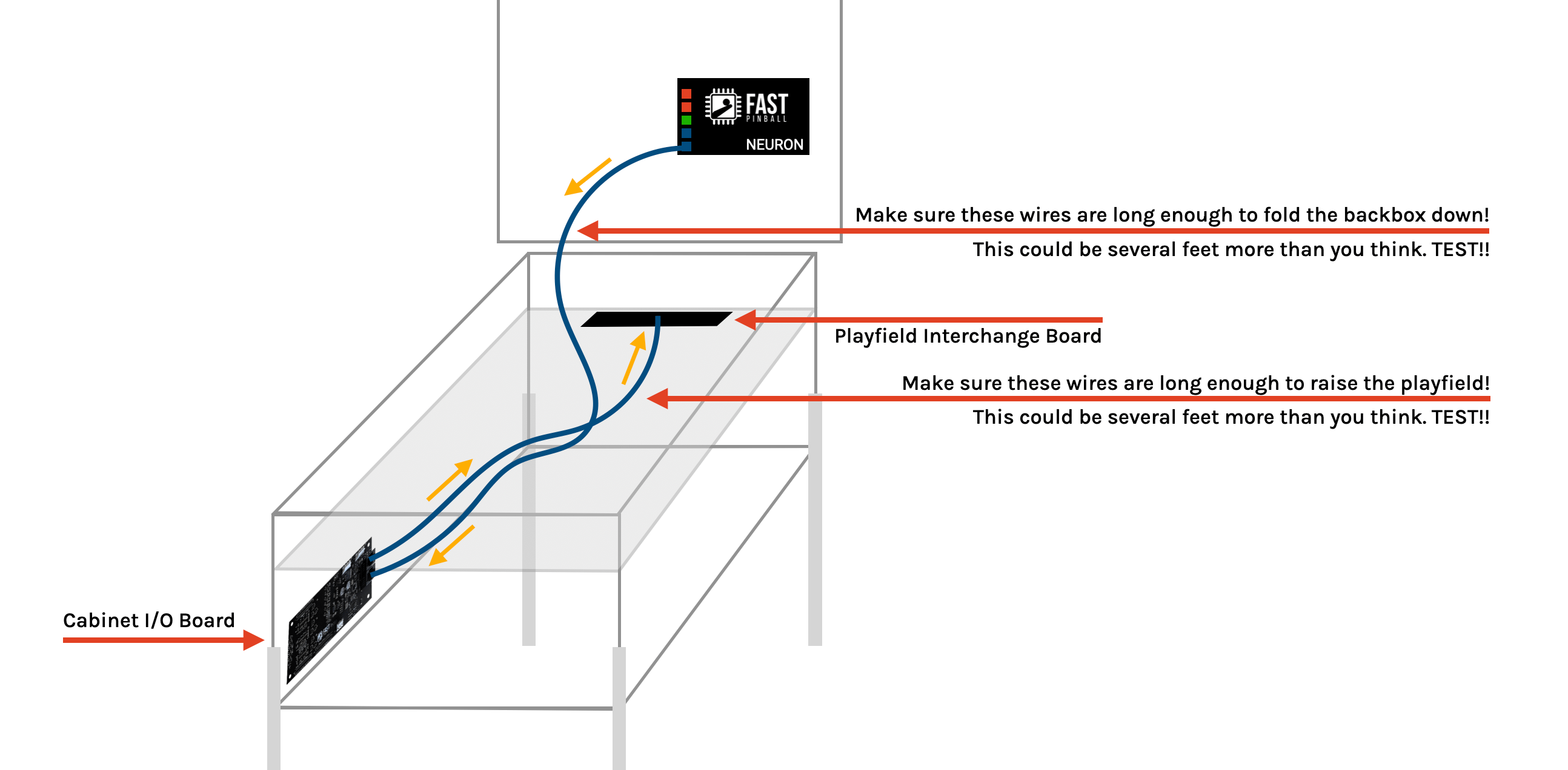
The previous guides on I/O Board and Playfield Interchange Board wiring show how the Cabinet I/O board is wired into the loop network. The Cabinet I/O board is just like any other I/O board, and you can wire it in the same way. It's designed to be placed in the front left corner of your cabinet. (Why left? Because that's the same side as the coin door hinge which makes it convenient to wire the coin door wires.) You'll typically run a Loop I/O Ethernet cable directly from the Neuron Out to the Cab I/O board In, and then from the Cab I/O board out up to the Playfield Interchange Board where it will continue on to the other I/O boards in your machine. (Or you can wire the Cab I/O board "last" in the loop. Your call, it makes no difference.)
Power input wiring
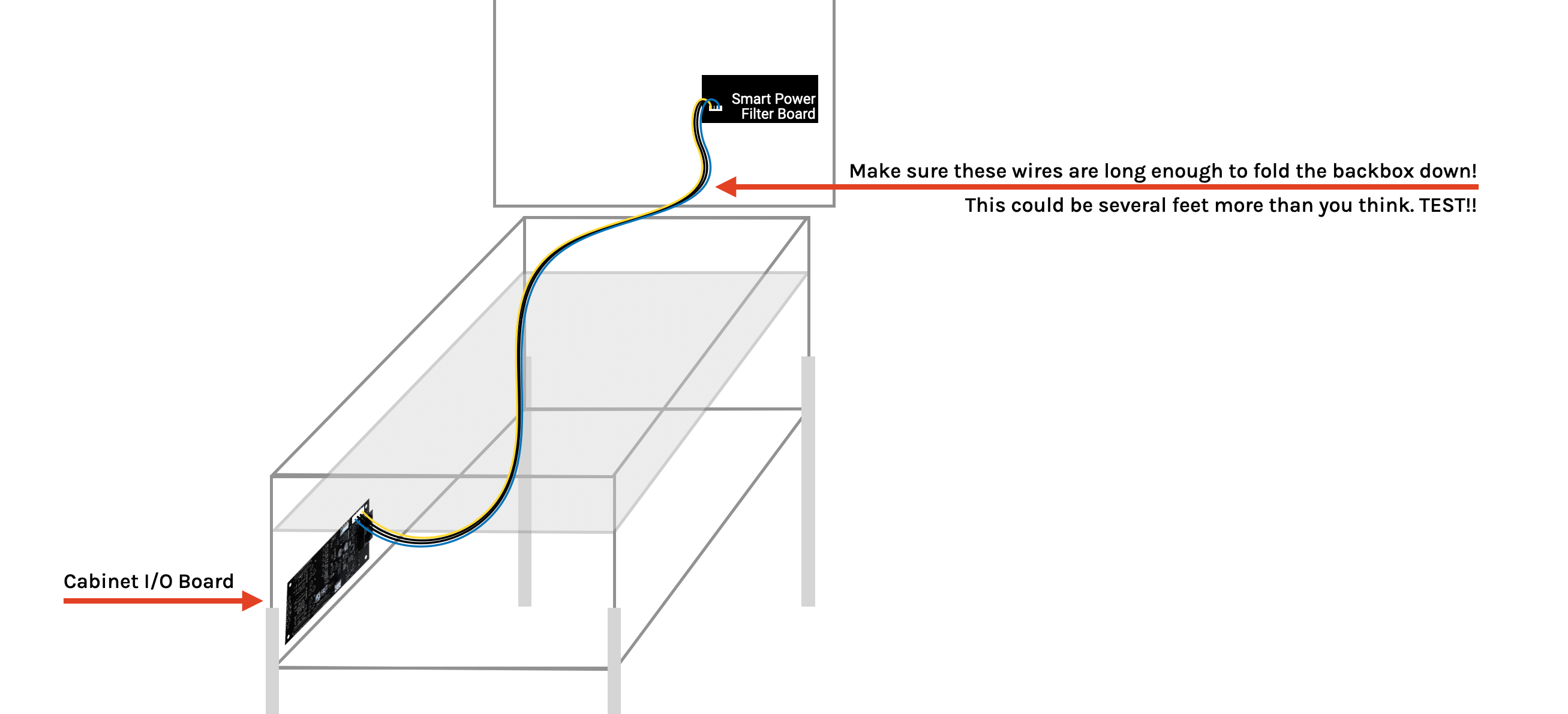
The Cabinet I/O board has a dedicated power input header J3 for 12V and 48V power. 12V is used for the low current drivers (LEDs, etc.), powering a bill/ticket/card reader, and other downstream 12V devices like a shaker motor or cabinet expansion board. 48V is used for the knocker coil driver.
This power comes directly from the Smart Power Filter Board which has an identical 4-pin header J10 specifically designed to power the Cabinet I/O board. That wiring was covered in our guide to Smart Power Filter Board wiring, so we won't cover it here in detail, but it will look something like this:
Cabinet Left / Right switch wiring
The Cabinet I/O board has two headers J1 and J9 for the cabinet's left side and right side switches and LEDs. These headers are identical (as is the coin door header covered next). Each header has the following pins which should provide you with the flexibility you need to wire that side of your cabinet's switches and LEDs:
- 12V power out (always on)
- 5V power out (always on)
- 2 low current driver outputs (for use with either the 12V or 5V power outs, for controlling LEDs or other low current devices)
- 8 standard switch inputs and 1 switch ground (for cabinet switches & buttons)
Typical cabinet switches include:
- Flipper buttons (possibly dual-stage, e.g. two switches per button)
- Start button
- Launch button
- Lockdown bar button
- Tilt bob
- Coin door interlock (that switch that disables the 48V power when the coin door is open)
- Other auxillary or novel buttons and switches? (Credit buy-in, Magna-save, diverter control, etc.)
LEDs are typically lighted start and/or launch buttons.
Flipper coils and EOS switches are not connected to the Cabinet I/O board
The Cabinet I/O board is just used for devices in the actual cabinet itself. So while the flipper buttons are in the cabinet, and therefore connected to this I/O board, the flippers themselves (their coils and EOS switches) are connected to different I/O board attached to the playfield.
Here's what a typical CABINET LEFT wiring might look like:
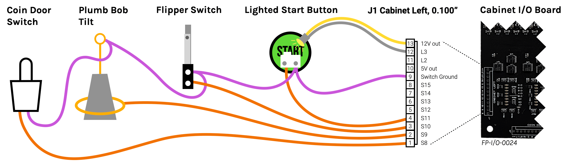
Note that the switches are wired up just like any other switch, with the purple common wire running to every switch, and then the each switch's other lug using orange wires back to their individual inputs.
If you have opto flipper buttons, you'd wire them like any other opto. You can grab 12V to power the optos from J11 (labeled SHAKER PWR) covered below.
Your CABINET RIGHT wiring will be similar. At a minimum you'll have the right flipper button, and possible a launch button, lockdown bar button, and other switches. You can wire them up just like the left side.
Of course the "left" and "right" headers are merely for convenience. You can use one, or both, or neither. You can use the left header for the right side switches, or vice versa. It doesn't matter. Just wire your cabinet switches to the pins you need.
Note that unlike most other headers in the FAST Pinball ecosystem, none of these headers have key pins. This is because we wanted to maximize the flexibility which meant providing as many pins as possible. If you're making a machine that will ultimately be owned by someone other than you, you might want to consider cutting off an unused pin from each header (pick a different pin for each) and using a key plug in the connector to prevent someone from accidentally connecting a cable to the wrong header. Luckily the actual pinouts of the four headers on the cabinet I/O board are similar enough that plugging the wrong connector into the wrong header shouldn't break things, it just wouldn't function as expected.
Cabinet LED wiring
The LEDs controlled by the cabinet I/O board are different than the RGB LEDs on the playfield. Cabinet LEDs used in lighted buttons and the coin door are typically single color, old-school bayonet-style or plug in sockets from the incandescent bulb days. They are usually powered by 12V, (though you can also get 5V ones), and they do not have polarity (they have some extra components inside to allow this and to power the LEDs properly).
You'll wire these LEDs like drivers, and you control them like drivers in your game software.
Remember with regular drivers, you run the blue 48V "always on" wire to each coil, and then use a white or gray driver control line from each coil back to an individual driver output on the I/O board. This same concept applies to these LED drivers from the Cabinet I/O board.
The Cabinet I/O board headers provide an "always on" 12V (via Pin 13 V+) or 5V (via Pin 10 5V). You run a common wire to each of your LEDs from whichever pin has the voltage you need. (Following the FAST wire color standards, you'd use a yellow wire if you're running 12V power, and a red wire if you're running 5V power.
Then run the other leg of each LED back to one of the low current driver control lines on Pins 11 or 12 using a white or gray wire.
What about RGB LEDs in the cabinet?
The Cabinet I/O board only provides driver outputs to control a few single-color LEDs. If you want modern RGB LEDs, such as stadium lighting in the cabinet walls, or under cabinet lighting, then you'd wire those like any other RGB LEDs in your machine using a Expansion Board in your cabinet. (See the LED wiring guide for more details.)
Coin door wiring
The first thing to know about pinball coin doors is there are absolutely no standards for pinouts, features, connectors, or anything else. The coin door vendors typically customize the wiring harnesses for the specific needs of each manufacturer, and even new or "drop in replacement" coin doors are all pretty different.
The coin door header J4 on the FAST Cabinet I/O board has same pins in the same order as the LEFT and RIGHT headers: 12V out, 5V out, 2 low current drivers, 8 switch inputs, and a switch ground.
You'll need to figure out what mix of these you need for your specific coin door, and then build a custom wiring harness or adapter to connect your coin door to the Cabinet I/O board.
The typical coin door wiring includes:
- 1-3 coin switches
- 4 service buttons (typically Up, Down, Esc, and Enter)
- Slam tilt (less common now, but still an option)
- LEDs in the coin reject buttons
If you coin door includes a bill acceptor, ticket dispenser, or card reader, that will have its own harness and wiring and is covered in the next section.
Wiring your coin door is fairly straightforward; you'll just have to break it down into the individual components and figure out which pins on the coin door header they connect to. Start with either a schematic or your meter and start mapping out what's what. (And of course the wire colors will vary wildly and have no relations to the colors of the wires inside your machine.)
Here's an example of how a typical coin door would be wired to the Cabinet I/O board (using standard FAST wire colors to keep things easy to follow):
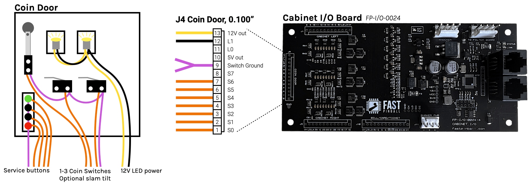
Let's step through each component and look at which pins on the coin door header they connect to.
Coin reject LEDs
The LEDs in the coin reject buttons are powered just like the single color LED that we described above. (And again, you can choose 12V or 5V, most are 12V.)
If you have more than one coin slot, most likely the LEDs will be wired in series (e.g. just a single power and ground wire shared by both). That's fine, as the cabinet I/O board provides enough power for several LEDs on the same driver output.
One novelty of using a driver output to control these LEDs is that you can control them in software. Unlike most machines, your LEDs will not automatically power on when the machine is on. Instead, you'll need to configure your game software to turn on the coin LEDs when it starts up.
You could actually have some fun with this. Maybe you make them flash when the machine is in attract mode? Or incorporate them into a light show? Or just turn them on when the game software starts up and call it good.
Coin switches
The coin switches on the coin door are just like any other switch in your machine, and you wire them just like any other switch. In this case, the purple switch ground return is Pin 9 G, and then you can use any switch inputs Pins 6-13 S0-S7 for these switches.
Some board revisions contain a misprint
Some cabinet I/O boards have a printing error where the switch input labels on the coin door are numbered 0-7-6-5-4-2-1-0 instead of 7-6-5-4-3-2-1-0. If you have one of those boards, just ignore the labels as the pins and electronics are correct, it was just a screen printing error.
Slam tilt switch
If your coin door has a slam tilt switch, it's also wired up just like any other switch. One purple wire to the Pin 9 G switch ground return, and the other wire to any switch input Pin 1-8 S0-S7. You can daisy chain the purple wire from your coin switches to the slam tilt switch, or run a separate wire from the slam tilt switch to Pin 9 G.
Service buttons
The service buttons are also wired up just like any other switches. Modern coin doors have a separate wiring header for the service buttons with a common wire and 4 individual wires for each button. Older style doors just use regular switches. Either way, it's the same wiring. Run a purple wire as the common (again either daisy chained from another location on the coin door or back from the Pin 9 G switch ground return), and then one wire for each button to any switch input Pin 1-8 S0-S7.
Coin door interlock switch wiring
Back in the Smart Power Filter Board wiring guide, we talked about the coin door lockout switch which is used to disable the 48V power circuits at the filter board when the coin door is open.
We highlighted that you have two options for wiring this:
-
A "smart switch" option where this switch is a normal switch going to your Cabinet I/O board, and then your game software controls the 48V power enable signal to the Smart Power Filter Board.
-
A "physical switch" option where you wire the coin door lockout switch directly to the Smart Power Filter Board.
The details of each of these are covered in that wiring guide linked above, but we're including this note here since the Cabinet I/O board is involved.
Smart switch option (preferred)
Since the Smart Power Filter Board is "smart", you actually don't even need to wire the coin door lockout switch to the Smart Power Filter Board at all. Instead, you can wire it to the Cabinet I/O board, just like a normal switch. (Just use a purple shared ground wire and an orange return wire and run it to either the left, right, or coin header on the Cabinet I/O board.)
When used in this way, the 48V will be disabled on power on since there's no enable switch connected. Then your game software can enable the 48V power when it's ready for it. (This is safer anyway because the filter board runs a watchdog, so if your game software crashes, the watchdog will time out and the 48V will be disabled.)
In this case, if the coin door is open, you can configure your game software to react to that switch event by sending the command to the filter board to disable the 48V, as well as notifying the player that the door is open. (You can also use the coin door open switch as a service button, e.g. to enter the service menu, or pause the game, etc.)
Physical switch option
If you're using the physical switch option, then the coin door interlock switch wires will run from the coin door lockout switch directly to the Smart Power Filter Board up in the backbox. In that case the Cabinet I/O board doesn't need to be involved in the wiring.
The Smart Power Filter Board has a header which simulates the switch status which you could plug into a switch input on the Cabinet I/O board if you wanted to get a switch notification of the door opening and closing. However, one of the "smart" parts of the smart power filter board is 48V current monitoring, so the board will know when its power gets cut off which the host computer can find out about via the Expansion Bus. So you don't really need to run the wires all the way down to the Cabinet I/O board if you don't want to.
Bill acceptor / card reader wiring
If you're building a machine for use in a commercial setting, you'll most likely have a bill acceptor (bill validator) or card reader. Wiring these is fairly straightforward as well, and the FAST Cabinet I/O board has a dedicated header J10 for these devices.
J10 changed between board revs FP-I/O-0024-3 and FP-I/O-0024-4
Prior to the -4 revision of this board, J10 was 11 pins and had a slightly different pinout. The function of the boards is the same, the additional pins are just for convenience. The -4 revision is the only version that's been sold publicly and most likely what you have. If you have an older board, you can still use it, just verify the label on the board for the pinouts.
Similar to the coin door wiring, there are no standards for the bill validator wiring, but if you focus on wires you actually need, it's pretty straightforward.
Choosing a bill validator
The most important thing for a bill validator in a FAST Pinball modern machine is to pick one that runs on 12 volts. There are multiple standards for validators, including 12, 24, and 48 VDC, as well as line voltage 120-240VAC. Obviously a validator that runs on something other than 12V means you need to find a way to get that voltage into your cabinet and it will probably be a pain. So get a 12V validator.
The other thing to look for is one with a "pulse" interface. (There are lots of ways the validator interfaces with the gaming machine, including digital standards, RS-232, etc.) The pulse interface is just a simple switch closure that happens when a bill is inserted and accepted. You configure the specific timing via the validator itself, e.g. if you insert a dollar, it pulses once, if you insert a $5 bill, it pulses 5 times. Or maybe you insert a dollar and it pulses 4 times and a $5 bill pulses 20 times, etc. The specifics don't really matter, since you just configure your game software to know the value of each pulse.
The specific validator we tested and used during the development of this board was the ICT V636-FOM-USD4-T2, available for about $250 from SuzoHapp and other distributors. But again, any validator that runs on 12V and has a pulse interface should be fine.
The following diagram shows the important pins on the validator that we care about. (Again, you'll need to either build an adapter, or cut off the connector it came with and wire in your own 0.100" header with the correct pin locations for the Cabinet I/O board.)
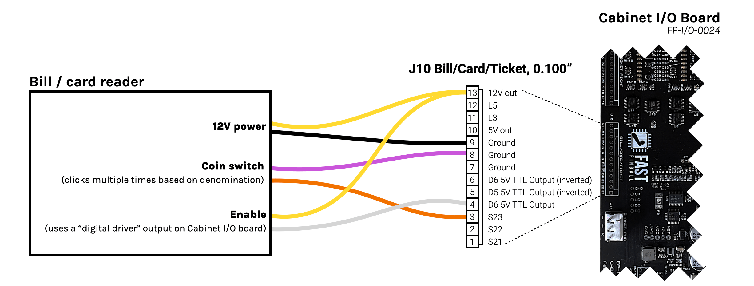
You'll want to use header J10 labeled BILL/CARD/TICKET on the Cabinet I/O board.
12V Power
The bill acceptor needs 12V to operate, which can be provided via J10 Pin 13. (This 12V power is protected and sized for the 4A required by the acceptor.) For the ground, use the ground from Pin 9.
Why Pin 9? Even though the 12V for the bill acceptor low current, it's more current than the switch circuits, so we like to use the ground that is physically closest to the 12V power. That minimizes the small voltage fluctuations exposed to the switches since it's a shorter distance to the 12V power. (Similar in concept to the conversations about the 48V toxic ground, but smaller and localized to this board.)
Pulse output (coin switch trigger)
The validator will send pulses to simulate switch closures associated with adding money to the machine. The exact name of this might vary depending on the model you're using. The one we tested called it CREDIT RELAY (N.O.) and CREDIT RELAY (COMMON)
You'll wire that up just like any switch, using a purple wire to Pin 7, 8, or 9 G, and an orange wire to one of the switch inputs on Pins 1-3. Most likely the "negative" or "common" will be your purple wire, and the "positive" or "normally open" will be your orange wire. But who knows how accurate the labeling is or if it even matters. Just try it, and if it doesn't work, swap the two wires.
Bill validator enable/inhibit
Most bill validators have some sort of input signal used to control whether or not they accept bills. This is used to prevent someone from putting money in a machine when the machine is broken or not fully booted up.
On the validator we tested with, these connections were labeled INHIBIT + and INHIBIT -.
You can read the documentation for your specific validator to understand how this enable signal should be wired. In our example, the enable is an opto isolated input which we can trigger with the TTL logic level digital driver output using Pin 4 D6 as the actual enable signal. If your validator enable is reversed, where it needs the signal to be active high to inhibit, then you can use Pin 6 D6 with the line over it which means "D6 NOT" (inverted) instead.
Connect the other side of the enable input to either Pin 13 V+ or Pin 10 5V depending on the voltage required by your validator. (The one we tested seemed to work with either.)
Then, sending a signal to enable that driver will enable (or not inhibit) the bill acceptor. On our test acceptor, enabling it caused little arrows to start flashing green on the front and it would accept bills. Disabling that driver (or disconnecting it) caused the LEDs on the front to turn off, and it would no longer accept bills.
There might be some other features in the validator, such as status pulses or other control lines. There are plenty of other outputs and inputs on this header if want to use them for various features of your validator.
Knocker (or other high current device) wiring
The cabinet I/O board has a dedicated header J2 for a knocker coil. This is a standard high current driver output, so you wire it up just like any other coil in your machine. (See the driver wiring guide for more details.)
You don't have to use this for a knocker, of course. You can use it for any high current coil in your cabinet. But if you are using a knocker, this is the easiest place to put it, since there aren't any driver control lines in the backbox.
Connect a blue 48V wire from Pin 1 H2 to one side of your knocker coil. Then connect the other side of the coil to Pin 4 D1 using a white or gray wire. The TG toxic ground pin is not used in this case since the board has an internal connection to the toxic ground. (That pin is included for other use cases where you might need access to toxic ground in the cabinet.)
Remember to install a diode across the coil, with the stripe facing the blue 48V wire.
The high current driver software number is 7
Even though the high current driver is labeled D1 on the board. In the software order, it's driver 7. (The various low current drivers are 0-6.) So in your MPF config, use driver number 7.
12V Shaker Power (or other high current 12V devices)
Finally, the Cabinet I/O board has J11 which is a dedicated 12V power output. Even though this header is labeled SHAKER PWR, you don't have to use it for a shaker motor.
(If you do use it for a shaker motor, the cabinet I/O board just provides the 12V power. You'll need to control it via a driver output (with proper protection) or via our motor controller board which connects to the expansion bus.)
You can use this 12V power output for any other high current 12V device in your cabinet. For example, you could use it to provide the 12V power for an expansion board to power cabinet RGB LEDs, a laser projector, or anything else you can think of that needs 12V.
N or > jump the next page, P or < for previous, search with S or ?