How to wire your FAST Neuron-controlled pinball machine
Wiring, high voltage, and electricity can be dangerous. Read this first!
The voltages and electricity discussed here can be dangerous and could cause property loss or death. It is your responsibility to ensure you are aware of these risks and comfortable with these processes. Furthermore your local jurisdiction may have regulations or rules which differ from what we discuss here, including wiring colors, standards, techniques, etc. Although based on broadly adopted methods, FAST Pinball does not employ Professional Engineers and this information is not professional recommendations. There may be errors, omissions, or typos here. Any pinball machine available to the general public should be reviewed by a licensed Professional Engineer in your region. Use this content at your own risk.
You're doing it!!! Congrats on starting your amazing journey to build a pinball machine! We are here to help you along the way. Part of that is this series of over 30 how-to guides which walk you step-by-step through the entire process of wiring a pinball machine powered by a FAST Pinball Neuron Controller.
This guide is for FAST Neuron-controlled machines only
This wiring guide is for pinball machines powered by a FAST Neuron Controller. If you have the prior model, the FAST Nano Controller, please use the Nano wiring guide instead.
"What goes where?" in a FAST modern pinball machine
Before we jump into the specific guides for each step of your machine wiring, let's take a look at the general wiring and board layout of a typical modern pinball machine powered by a FAST Neuron Controller. The diagram below shows a high level overview of what goes where. (Obviously you are free to design your own pinball machine however you want. This just shows the typical machine and how we envision everything coming together.)
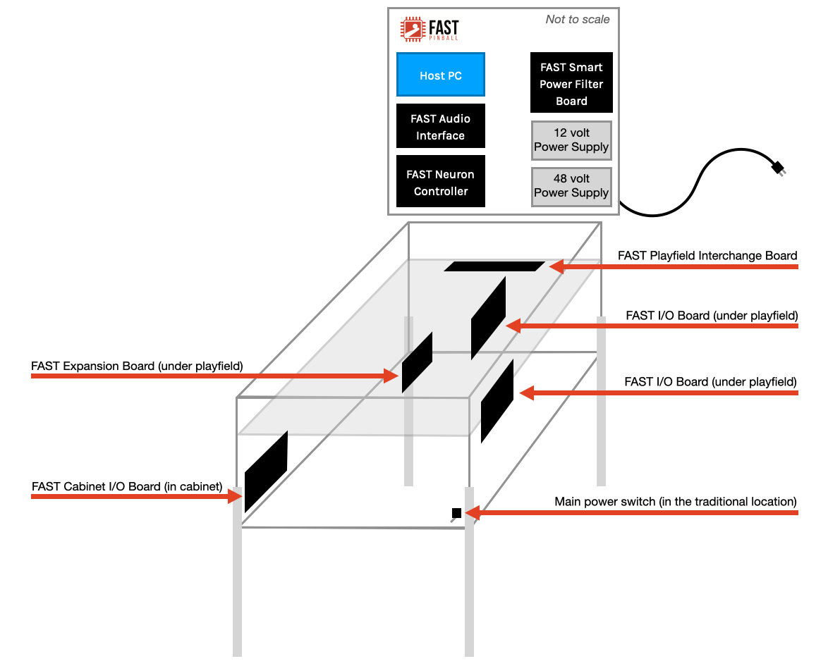
Let's walk through this diagram and look at the details of each section of your machine.
The backbox
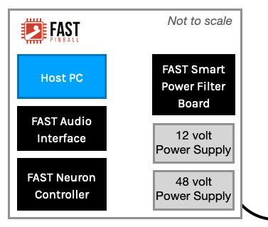
The main power cord connects into the backbox, where two power supplies convert the incoming AC power to 48-volts and 12-volts DC to run your machine. (FAST Neuron controlled pinball machines do not require 5-volt power supplies, as any boards that need 5 volts generate it on their own from the 12-volts.)
The FAST Smart Power Filter Board collects the 48-volt and 12-volt power from the power supplies, provides fuses and capacitors to keep the voltage up during busy machine moments, and has various headers to distribute the needed power to various other parts of the machine. This board is "smart" in that it provides current and fuse monitoring (via a connection to the Neuron), and it can cut off the 48-volt power if it detects a short or other over-current situation.
The FAST Neuron Controller is also located in the backbox. It connects to all the other boards in the backbox, and also has LED ports to control LEDs in the backbox.
The FAST Audio Interface is the "sound card" for your machine, which includes amps for the backbox speakers, cabinet subwoofer, and a headphone interface. It's controllable via software so you don't have to open your machine to adjust the volume or other audio balance settings.
Your Host PC is the computer which runs your pinball game software and controls the whole machine. This can be a "real" computer, or a compact system (e.g. Intel NUC, etc.), or even a Raspberry Pi. This is where the Mission Pinball Framework (or whatever game framework you're using) runs. It can be Linux, Mac, or Windows. Any LCD displays you have will run off of HDMI ports from this computer.
(Not Pictured) A modern-style machine will have a speaker panel which will include 2 speakers and an LCD or DMD display. Or you could build a machine with segment displays which you might locate on the light board.
(Not Pictured) If you want to build a topper, you can either power it with breakout boards connected to the Neuron, or with an expansion board connected to the Neuron via the EXP Bus.
The Playfield
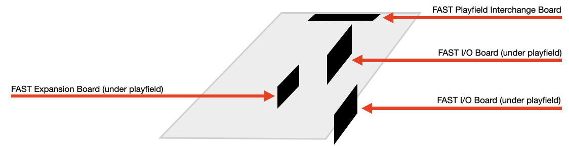
Modern FAST Pinball machines use FAST I/O Boards for switches and drivers. There are various models of these boards which have different numbers of each, and you can mix-and-match them as you need. I/O Boards are mounted under the playfield (typically vertically) and are "local" to the switches and drivers as needed. Typical machines have 2-3 I/O boards under the playfield. (In a FAST Neuron-controlled machine, there are no restrictions for keeping related drivers and switches on the same board. Any switch can control any driver on any board.)
LEDs, servos, steppers, flashers, and other bling are connected to FAST expansion boards. There are also different models with different numbers of ports and connections, and many have additional breakout board headers to connect more things. You will most likely just have one of these under your playfield, though there could be more depending on your needs.
The FAST Playfield Interchange Board is a small board you mount to the rear of your playfield. All of the wires that connect the playfield to the machine go through this board, so if you need to remove the playfield, you just have to unplug a few connectors here and it comes right out. This board also receives power from the Smart Power Filter board and acts as a power distribution point for the playfield, with multiple breakouts for 48V, 12V high current, and 12V low current (for optos, etc.)
The Cabinet
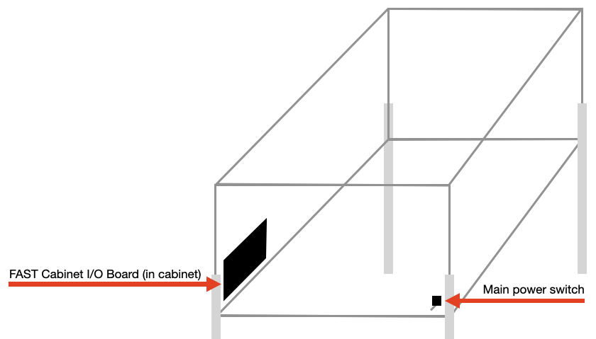
Your machine's main power switch can be located in the traditional location under the right-front corner of the cabinet. The FAST Neuron includes "soft power switch" technology which lets the Neuron control your machine's power. (This has the added bonus of keeping high-voltage AC power out of your cabinet but still have the switch in the normal location!)
The FAST Cabinet I/O Board is similar to the other I/O boards under your playfield, except it's specifically designed for your cabinet. It includes switch inputs for all your cabinet switches (flipper buttons, start, launch, tilt, service buttons, etc.), as well as providing low-current drivers for flashing LEDs in buttons, and an option to connect a knocker coil. This board also has a coin door interface.
(Not Pictured) You'll most likely install a subwoofer in the bottom of your cabinet.
(Not Pictured) If you want to do exterior lighting, or long strips of LEDs embedded into the sides of the cabinet above the playfield, then you'll use a FAST expansion board in your cabinet to drive those.
Step-by-step wiring guides
Now that you have a general sense of the overall machine layout, let's dig into the detailed guides for each step. Before starting, we have important pre-read guides which you should read first:
- What wire should you use?
- Ohm's law, wire resistance, and non-zero grounds
- Skill basics: How to crimp wires
Next, here are the step-by-step guides for each step of your machine wiring. You don't necessarily have to follow them all in order. (And in fact not every guide will apply to every machine.)
- AC line in & power supply wiring
- SSR & soft power switch wiring
- Smart power filter board wiring
- Ground wiring
- Fuses & current calculations
- Neuron Controller wiring
- Playfield interchange board wiring
- Playfield I/O Boards
- Cabinet I/O Board
- Switch wiring
- Opto wiring
- Driver & coil wiring
- Flipper wiring
- Expansion Board Wiring
- LED wiring
- Audio interface & speaker wiring
- Shaker motor wiring
- Stepper motor wiring
- Servo wiring
- Magnet wiring
- Host computer wiring
- Raspberry Pi wiring
- LCD display wiring
- Segment display wiring
- RGB DMD wiring
- Cabinet lighting
- Wire management & routing
N or > jump the next page, P or < for previous, search with S or ?