How to wire expansion boards in a FAST Neuron-controlled pinball machine
Wiring, high voltage, and electricity can be dangerous. Read this first!
The voltages and electricity discussed here can be dangerous and could cause property loss or death. It is your responsibility to ensure you are aware of these risks and comfortable with these processes. Furthermore your local jurisdiction may have regulations or rules which differ from what we discuss here, including wiring colors, standards, techniques, etc. Although based on broadly adopted methods, FAST Pinball does not employ Professional Engineers and this information is not professional recommendations. There may be errors, omissions, or typos here. Any pinball machine available to the general public should be reviewed by a licensed Professional Engineer in your region. Use this content at your own risk.
FAST expansion boards are used to control everything in your machine that's not a switch or driver. (Switches and drivers are special, since they have to be so quick, which is why they have their own boards and their own bus.) Things like LEDs and servos are connected to expansion boards and use the FAST Expansion Bus.
There are different models of expansion boards which support different amounts and types of devices. Similar to the I/O boards, you'll most likely have multiple expansion boards throughout your machine.
You'll have at least one expansion board under your playfield to drive playfield LEDs and servos. You might have another one in your cabinet, which would control a shaker motor or drive under cabinet or stadium lighting. If your machine has a topper, you'll most likely have an expansion board inside to control it.
And what about the backbox? Actually, the Neuron controller has a built-in expansion board! Those 4 LED ports, and the 3 breakout connections, are technically an expansion board which connects to the expansion bus. (You'd use this expansion board to drive backbox LEDs, connect to the smart power filter board, and to drive any interactive backbox features.)
Wiring guides for the actual "things" you use your expansion boards for are covered in their own future guides. (Wiring guide to LEDs, Wiring guide to servos, etc.)
The remainder of this guide shows you how to wire the actual expansion boards themselves, which you'll need to do first before connecting the things from the future guides.
The Expansion Bus
The FAST Expansion Bus is a tree topology network of Ethernet cables that connect all the expansion boards to the Neuron. The expansion bus is not a loop, you just need to get every board connected to another. Many expansion boards have two EXP Bus ports, which you can use to daisy-chain boards together.
There is no orientation, direction, or order for the expansion bus cables. You can plug anything into anything in any order. The following diagram shows an example of how the Neuron and various expansion boards can be connected.
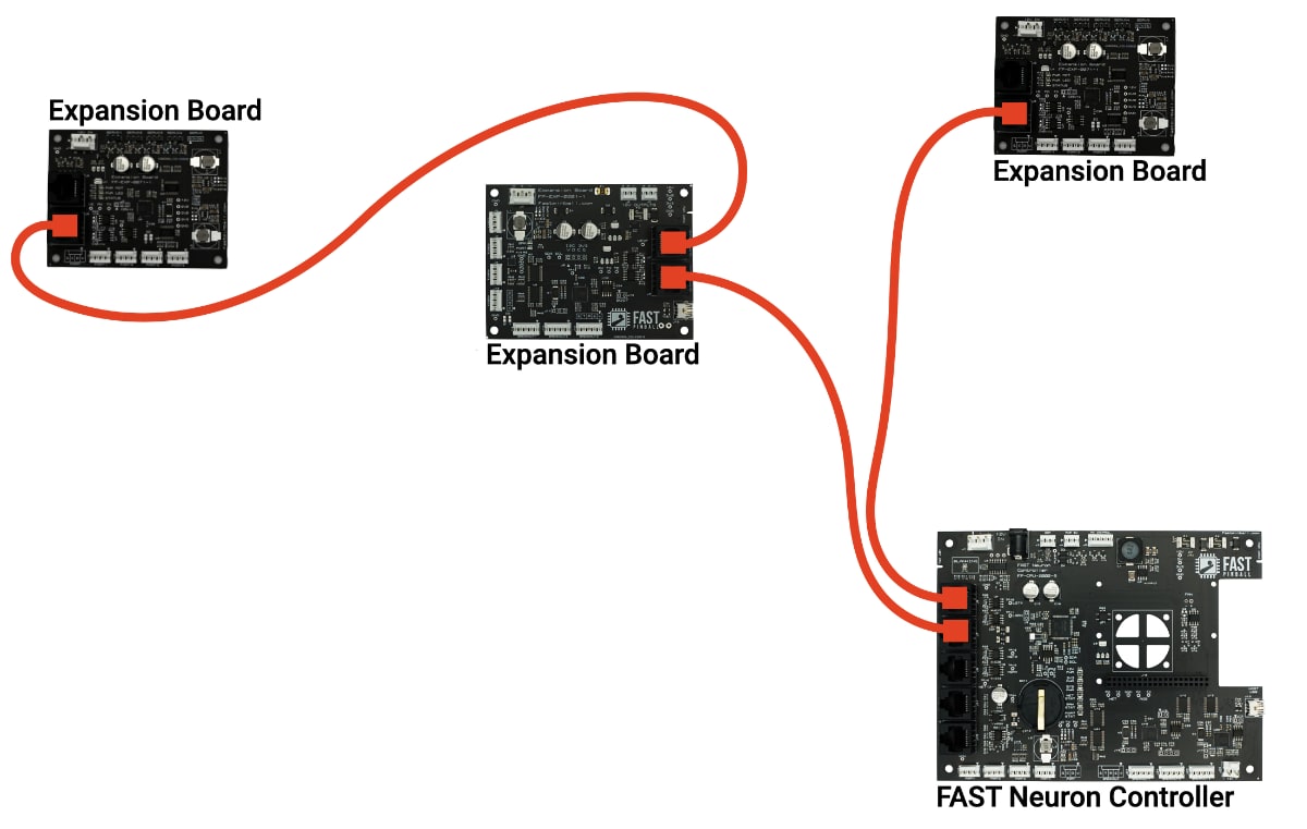
Again, the expansion bus is not a loop. You do not need to use every port.
Expansion board ID solder jumpers
Every different type of expansion board has its own address on the FAST expansion bus which hard-coded into its firmware. This is how a board knows which messages to respond to. If you have multiples of any single model expansion board, then you can solder some jumpers to give each one a unique identity.
For example, if you have two expansion boards, an FP-EXP-0071 and an FP-EXP-0081, then you don't need to do anything with the jumpers since those are two different boards. But if you have two FP-EXP-0071 boards, then you would need to solder one of the ID jumpers of one of the boards. (Note that the last portion of the product number is just the hardware revision and not an element of the part number. e.g. FP-EXP-0071-0 and FP-EXP-0071-1 are two of the same board as far as the configuration is concerned.)
The diagram below shows what the ID solder jumpers look like. Their location varies depending on the board.
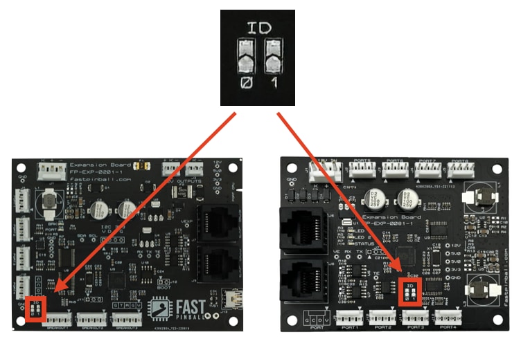
The ID jumpers are 2 regular bits. An X in the chart below represents a jumper that you soldered closed. (Use solder to connect the two halves of a jumper to set it.)
| Jumper Bit 0 | Jumper Bit 1 | Resulting Board ID |
|---|---|---|
| 0 | ||
| X | 1 | |
| X | 2 | |
| X | X | 3 |
Changing the ID of one of your expansion boards will change its address on the bus, which is something you'll need to know when you're setting up your game software. If you're using the Mission Pinball Framework, you can read about expansion board addressing in MPF config files here. And if you're writing your own framework, read about this in the EXP processor overview section of the FAST Serial Protocol documentation.
For now, just know that if you have two of the same board that you need to change one of the values via the ID solder jumpers.
Breakout board concepts & wiring
If expansion boards are branches on the expansion bus network tree, breakout boards are their leaves. The breakout boards are where the actual devices are connected, like LEDs or servos. Every expansion board has a "local" breakout board built-in, and many expansion boards have breakout ports which are used to add additional breakout boards.
For example, a small LED breakout board could add another 128 RGB LEDs to any expansion board with a breakout port. Or if you recall from the smart filter board wiring guide, the expansion board that's built-in to the Neuron controller has 3 breakout ports, one of which you use to make the smart connection to the filter board. In other words, the FAST smart power filter board is a breakout board for the expansion bus.
Breakout boards can be custom made as well. For example, using the breakout board concept could be useful for custom light boards or other small boards that might power a smart mod or toy.
Similar to the expansion board wiring, the actual instructions for wiring breakout boards are in the relevant wiring guides for the type of device you're connecting.
Wiring your expansion boards in your machine
The physical wiring of your expansion boards includes the Expansion Bus wiring as well as 12V power. (Again, the things like LEDs and servos you actually attach to the expansion boards are covered in future guides.)
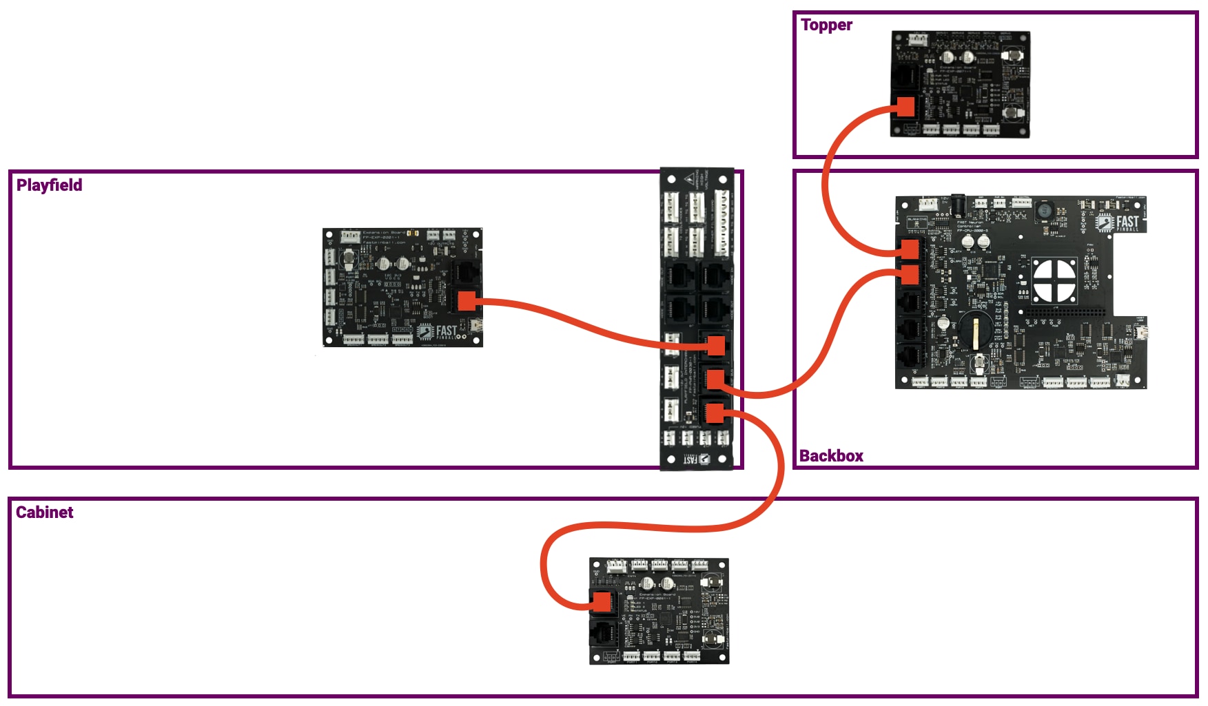
The expansion bus wiring will be similar to the diagram from the beginning of this guide, except you'll have to think about the logistics of what connects to what. There is no difference from a performance standpoint, it's really just about finding a cable routing path that makes sense.
For example, here's a typical machine which shows how the expansion bus uses the 3 EXP BUS ports on the playfield interchange board. One of them comes from the Neuron, one goes to a playfield expansion board, and the other down to the cabinet.
Expansion board 12V power
Most expansion boards require 12V high current power. In the FAST Modern platform, 12V high current power uses 0.156" 3-pin headers. They're rated for a max of 7A and require at least 18 gauge wire.
This 12V power is used both to power the logic on the expansion boards, as well as to provide the power for the devices which are connected to the expansion board. (This voltage is stepped down on the board as needed. For example, LEDs run on 5V, and servos use 6V, all which comes from the 12V power header on the expansion board.)
The following diagram shows how the expansion boards from the prior diagram would receive their power.
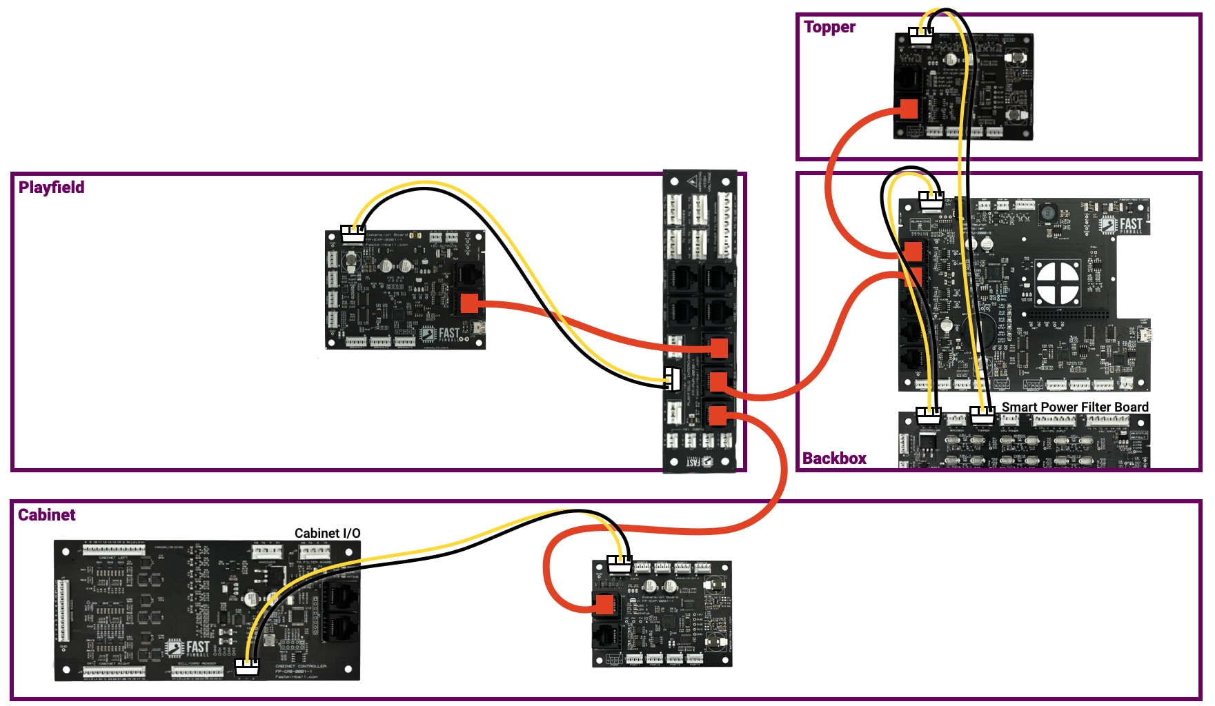
- The topper expansion board uses the
TOPPER12V header on the Neuron. - The backbox expansion board (built-in to the Neuron) gets its power from the 12V input which powers the Neuron.
- The playfield expansion board uses one of the 12V high current headers on the playfield interchange board.
- The cabinet expansion board can use the 12V output header on the Cabinet I/O board.
Pretty straightforward!
N or > jump the next page, P or < for previous, search with S or ?