How to wire your audio interface and speakers in a FAST Neuron-controlled pinball machine
Wiring, high voltage, and electricity can be dangerous. Read this first!
The voltages and electricity discussed here can be dangerous and could cause property loss or death. It is your responsibility to ensure you are aware of these risks and comfortable with these processes. Furthermore your local jurisdiction may have regulations or rules which differ from what we discuss here, including wiring colors, standards, techniques, etc. Although based on broadly adopted methods, FAST Pinball does not employ Professional Engineers and this information is not professional recommendations. There may be errors, omissions, or typos here. Any pinball machine available to the general public should be reviewed by a licensed Professional Engineer in your region. Use this content at your own risk.
Coming soon!
This section of the documentation is not yet complete and will be coming soon. However, if you need this now, and/or you want to share what documentation is most important to you, please post to the #docs channel in the FAST Pinball Slack community. Thanks!
This guide shows you how to wire your speakers and the FAST Audio Interface in a Neuron-controlled pinball machine.
Do you need to use the FAST Audio Interface?
Any modern pinball machine playing audio from a computer will need some kind of audio amplifier. (e.g. you can't just plug the speakers into the headphone jack on your computer.)
Historically, homebrew and boutique pinball makers have used generic external audio amplifiers. There are hundreds of options for under $50 on Amazon which are all more-or-less "fine". The FAST Audio Interface is similar in concept, but specifically designed for use in pinball machines. This wiring guide will show you how to use the FAST Audio Interface in your machine.
What does the FAST Audio Interface offer versus a random Amazon amp?
The FAST Audio Interface is an analog stereo amplifier designed for use in in a pinball machine running the FAST platform with the following features specific to pinball machines:
- The volume levels are controlled via software, so you can use buttons, a front panel, or your game software to control the volume. This is more convenient than opening the machine to turn a knob to change the volume.
- The headphone detection mechanism uses impedance detection, not a mechanical plug insertion switch, so headphone detection works through an extension cable and a headphone jack on the front of your machine.
- The behavior of what happens when the headphones are connected is configurable.
- There's a header to control the "soft buttons" of an LCD display. (e.g. if your display requires a separate power on button press, or series of button pushes to select the proper input, this can be controlled and automated by your game software via the audio interface.)
- The input power comes directly from the Neuron or filter board. You don't need a separate power supply or wall wart.
- 12V output power headers provide downstream power to devices (like the LCD).
- It's designed to be mounted in the machine as a circuit board, rather than a separate enclosed box. (And it matches the rest of the boards you have in your machine.)
- Audio controls are standard FAST Serial Protocol commands, like the everything else in the FAST ecosystem. Integration with the Mission Pinball Framework is already done for you, and integration with other frameworks is easy.
Limitations of the FAST Audio Interface
Even though it was designed specifically for use in pinball machines, the FAST Audio Interface is not right for everyone.
First, it's just 2-channel stereo. If you want 4-channel surround sound, this isn't for you.
Also, audio input is analog. This means your host computer will need a sound card, and the DAC in your host computer or sound card will be used to generate audio. If you want a digital audio solution, you'll need to look elsewhere.
The FAST Audio interface requires 4-ohm speakers. (This is what's standard in the pinball industry.) If you want to use 8-ohm speakers, you'll need a different solution.
Finally, the FAST Audio Interface provides about usable 15 RMS watts per channel. That's still 60W total (2 speakers and a dual-voice sub), which really is plenty for a pinball machine and sounds great. But if you want to really shatter some windows and build a bumpin' machine, you'll want to use audio devices from the car stereo community when support more power.
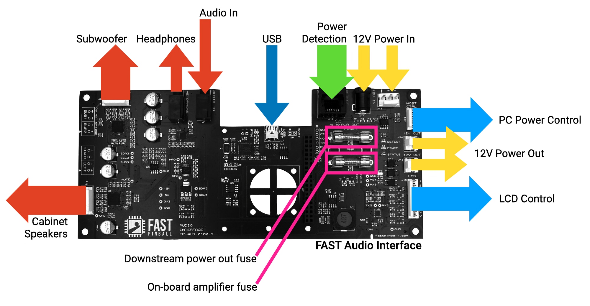
How the audio interface works
- Takes stereo audio from your host computer.
- Has three amps: One for the backbox speakers, one for the cabinet subwoofer, and one for the headphones.
- Controlled and configured from the host computer via USB. Note that the USB connection is only for control, it does not carry audio.
This guide is for modern (new) machine wiring only
The FAST Pinball Audio Interface is somewhat of a "dual use" device. It can be used in new, modern platform machines, as well as in retro machines (where it provides a modern audio platform alongside a FAST Retro Controller). This guide you're reading is for Neuron-controlled machines, so we'll only be covering the modern machine use case. This means that some features on the audio board will not be used, and not covered here.
- The Raspberry Pi header is not used in a modern machine. If you're using a Raspberry Pi for your host computer, you'd plug it into the Neuron, not the Audio Interface.
- The Host Control (
J16) header is not used, as the Neuron has the same feature, and you'd use that instead. - The power on detect feature (RJ-45 Jack
J10) is not needed in modern machines. This is used in retro machines to so the audio interface knows when to power itself on and off, for scenarios where it's powered via a separate always-on power supply from the service outlet. But in a modern machine, the audio interface receives power from the power filter board only when the machine is on.

12V Input Power
The FAST Audio interface runs on 12V. Similar to the Neuron, there are two 12V input connectors: a barrel jack (J10) and a 3-pin 0.156" header (J11). You can use either one (not both), though in a modern Neuron-powered machine, the intention is you'd use the 3-pin header. (The barrel jack is intended for use in retro machines, where the audio interface is typically powered from a separate plug-in power supply.)
In a modern machine where the Neuron and audio interface are both in the backbox, you'll most likely power the audio interface from the 12V power out header on the Neuron (J26). This was covered in the Neuron wiring guide.
If you power the the audio interface from somewhere else, ensure that it's protected by a fuse with a maximum rating of 5 amps.
Power on detection & behavior
If you're playing with the audio interface, you might be confused as to why it's not powering on, even though you have 12V in.
This is because the audio interface has detection circuitry and will only power itself on when it detects that the rest of the FAST platform is powered on. So you need to either:
- Connect the RJ-45 jack to the EXP or DSP bus, or
- Drop a dab of solder across solder jumper
JP1.
Using the RJ-45 jack for power on detection
This detection circuitry uses the RJ-45 jack, connected to either the EXP bus or DSP bus. In fact, that's the only purpose of the RJ-45 jack. The audio interface doesn't actually use the EXP or DSP bus for communications, it just uses it to detect when the rest of the platform is powered on.
So in order to power on the audio interface, you need to connect the RJ-45 jack to the EXP or DSP bus.
Using the solder jumper for power on detection
If you don't want to waste a Cat-5 cable just for power detection, or if you actually need to use all the EXP and DSP connections for other things, you can use the solder jumper JP1 on the audio interface to disable the power on detection circuitry. This will cause the audio interface to power on as soon as it receives 12V power.
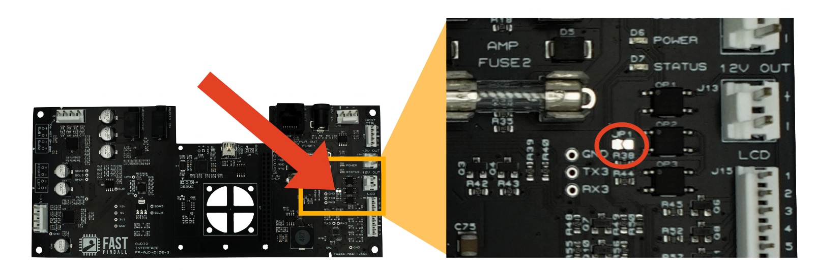
To do this, just drop a dab of solder across the two pads of JP1, and now your audio interface will behave as expected and turn on whenever it receives power. (This is how it's intended to be used in a modern machine. The power on detection is only needed in retro machines, where the audio interface is powered from a separate power supply that's always on.)
Speaker selection
Sections from here down are not yet written . . .
PC host control
LCD panel control
Using the headphone jack
Note that this can be set to line level or headphone level.
Addressing hum and buzz
Volume levels from your host PC
N or > jump the next page, P or < for previous, search with S or ?