Intro to FAST Pinball EXP Bus programming
FAST expansion boards are controlled via the FAST Serial Protocol connecting to processors over the FAST expansion bus. These processors will identify themselves as EXP processors via the ID: command.
FAST expansion boards are supported on all current FAST platform controllers. (The Neuron and Retro controllers have EXP ports on them. An EXP port can be added to the FAST Nano controller via an expansion hat.)
Understanding the expansion board communication architecture
Communicating with EXP processors over the expansion bus is a bit different than other FAST processors and connections since there can be multiple expansion boards on the same bus, each which could have one or more breakout boards. This means most EXP commands must be addressed to the specific expansion board + breakout board for the device you want to communicate with.
There are two ways to target expansion board + breakout combination. (1) You can embed an address into the command, or (2) you can set a particular board to be "active" and then every subsequent command you send applies to that board until you set a different board to be active.
Let's look at the concept of addresses first, then we'll look at how to use them.
Expansion board addresses
Each different model of a FAST expansion board has a unique address built-in to its firmware. In situations where you have more than one of a single type of board in a machine, there are solder jumpers you can use to set a variation of the address so your game code can identify each board separately.
For example, if have a a machine with two FP-EXP-0071 boards (maybe one under the playfield and another in a topper), the default address for that board is B4, so you could solder the ID jumper 0 on the second board which would give it the address B5.
The following chart shows the addresses of each expansion board for their various IDs. You only need to change the ID setting if you have more of one of the same type of expansion board in a machine. The jumper numbers use bit math to set the ID. The boards are ID 0 by default (no jumpers soldered).
| Board Type | Logical ID | Address | Jumper 0 | Jumper 1 |
|---|---|---|---|---|
| Neuron | N/A | 48 | N/A | N/A |
| FP-EXP-0071 | 0 | B4 | ||
| FP-EXP-0071 | 1 | B5 | ||
| FP-EXP-0071 | 2 | B6 | ||
| FP-EXP-0071 | 3 | B7 | ||
| FP-EXP-0081 | 0 | 84 | ||
| FP-EXP-0081 | 1 | 85 | ||
| FP-EXP-0081 | 2 | 86 | ||
| FP-EXP-0081 | 3 | 87 | ||
| FP-EXP-0091 | 0 | 88 | ||
| FP-EXP-0091 | 1 | 89 | ||
| FP-EXP-0091 | 2 | 8A | ||
| FP-EXP-0091 | 3 | 8B |
Breakout board addresses
While some FAST Serial Protocol commands on the EXP bus apply to expansion boards, all of the various devices you communicate with (LEDs, servos, etc.) are technically connected to breakout boards. Therefore most of the addresses you use will be a combination of the "parent" expansion board along with the specific breakout board the device is attached to.
Most FAST expansion boards have a breakout board 0 built into them which controls the devices connected to the expansion board itself. Some expansion boards have additional headers used to connect to additional breakout boards to add more devices to the expansion board.
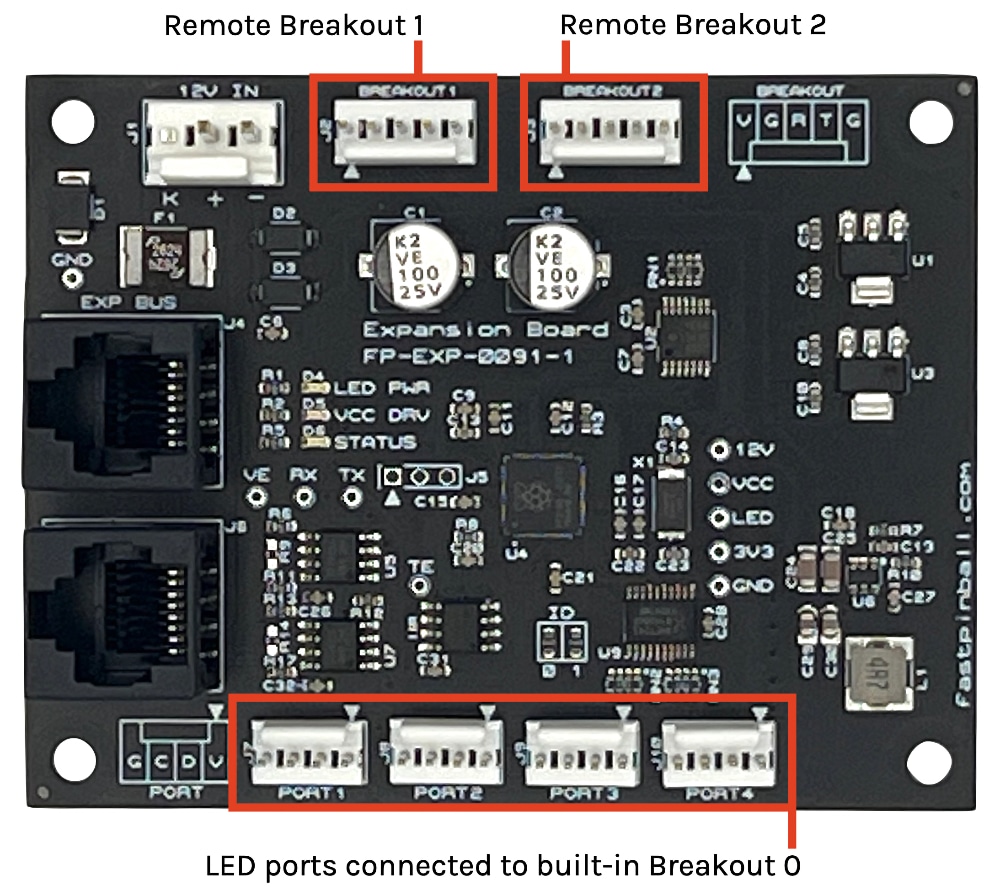
The diagram of a FAST FP-EXP-0091 expansion board below illustrates this concept. This board has four built-in RGB LED ports (which can contain chains of up to 32 LEDs each). Those four LED ports are running on the onboard "breakout board 0". If you want to drive more than 128 LEDs from this expansion board, you can add an LED breakout board which would connect to one of the breakout broad headers.
This modular architecture allows pinball makers the flexibility to configure their FAST hardware for the exact device types and counts they need. It also allows for custom breakout boards to be built for specific scenarios. (For example, maybe you have a few lighting boards with lots of LEDs on them. We can then design a custom LED board that acts as a breakout board and connects directly to one of the Breakout headers on an expansion board.)
Breakout boards are individually addressable via a single nibble (0-5) added to the end of the expansion board address. Some examples are shown below:
- FP-EXP-0091 expansion board at ID 0 (Address
88), Onboard Breakout 0 (Address0) =880 - FP-EXP-0071 expansion board at ID 1 (Address
B5), Onboard Breakout 0 (Address0) =B50 - FP-EXP-0091 expansion board at ID 3 (Address
8B), Remote Breakout 2 (Address2) =8B2
The Neuron Controller has a built-in expansion board too!
You may have noticed from the table above that there's an entry for the FAST Neuron Controller. That's because the Neuron has an expansion board built into it. So those 4-ports of LEDs on the Neuron are controlled via the Expansion Bus, using the Neuron's address 48. The built-in LED ports are breakout board 0, and then there are also three additional breakout board headers for additional connections. (The FAST Smart Power Filter Board connects to one of these, for example.)
What do you do with these addresses?
Now that we've looked at how expansion boards and their breakout boards are combined to get the full address for a device, let's look at how you use them. There are two options:
- Embed the address into a FAST Serial Protocol Command
- Set the "active" board, then send normal commands
Let's look at each.
Embedding Expansion+Breakout addresses into a command
Most FAST Serial Protocol commands for expansion and breakout boards can take an address parameter embedded into the command itself. Let's look at a simple example, using the ID: command. (All of these examples are valid only on the EXP bus)
ID:Since this does not have an address embedded, one of the connected expansion boards will respond indicating the active connection is to an EXP bus.ID@88:This is addressed to the FP-EXP-0091 expansion board with no solder jumpers. If you have one of these boards plugged in to your EXP Bus, then this board will respond with its ID. (If the address is not valid for a board that's connected, there will be no response.)ID@881:This is addressed to the remote breakout board connected to Breakout 1 on that same expansion board. If a breakout board is attached, its processor will respond to thisID:command. If there is no breakout board attached to Breakout 1, then this command will have no response.
Most (but not all) commands can have an address embedded into them. For example:
RA@880:005500 Turn all LEDs medium green, for LEDs attached to the built-in breakout board 0 (e.g. the 4 built-in LED ports) on an FP-EXP-0091 with no solder jumpers set.
Note that the address in the above command is 88 + 0, singling out the specific breakout board on that expansion board. If you tried the command RA@88:005500 (address 88 instead of 880, then this command work at the expansion board level, meaning that all LEDs attached to all breakout boards on that expansion board would turn green.)
Setting an Active Expansion + breakout board
Instead of embedding the Expansion + Breakout address into every command, you can set a specific Expansion or breakout board to be "active", and then all subsequent commands without an address embedded in them are received by the active board.
An active board is set with the EA: command. The EA: command does not provide a response.
Here's the same example from above, used to turn all the LEDs from Breakout 0 on an FP-EXP-0091 expansion board light green: (Every line ends in a <CR> which is not shown)
ea:880
ra:005500
You can also use the two-character expansion board addresses like this. To reset all LEDs attached to the four onboard Breakout 0 ports, as well as any devices attached to any of the three remote breakouts, you would use the following sequence: (Every line ends in a <CR> which is not shown)
ea:b4
br:
Which addressing method should you use?
From a pure technical standpoint, it doesn't matter whether you use commands with the board address embedded versus setting the active board address and then using the shorter commands with no addresses in them. It really just depends on which method is more convenient based on the architecture of the game software you're writing.
For example, the Mission Pinball Framework mostly uses the "active board" method. To use the LED updates as an illustration, MPF maintains a list of "dirty" LEDs that need to be updated every frame. (e.g. 30 times a second). When the LED update process wakes up to update the LEDs, it scans through all the LEDs in the code to see which ones need to be updated, then it arranges them all by breakout board, then it walks through the breakout boards, setting the active board, updating the LEDs, and repeating until it's done.
For example, let's look at a pinball machine with the following LEDs connected:
- Neuron Controller, onboard LED ports (Breakout 0), address
480 - Neuron Controller, LED breakout board connected to Breakout 2, address
482 - FP-EXP-0091 expansion board, onboard LED ports (Breakout 0), address
880 - FP-EXP-0091 expansion board, LED breakout board connected to Breakout 1, address
881
If you look at the actual serial commands for the EXP bus that MPF would use to update LEDs each frame, it might look like this:
ea:480<cr>
rd:02<binary LED update data>
ea:482<cr>
rd:04<binary LED update data>
ea:880<cr>
rd:1A<binary LED update data>
ea:881<cr>
rd:78<binary LED update data>
N or > jump the next page, P or < for previous, search with S or ?