FAST Audio Interface Board
Part Number: FP-AUD-0100
This product is not yet released
This documentation is for a product that is not yet released. Final details may change.
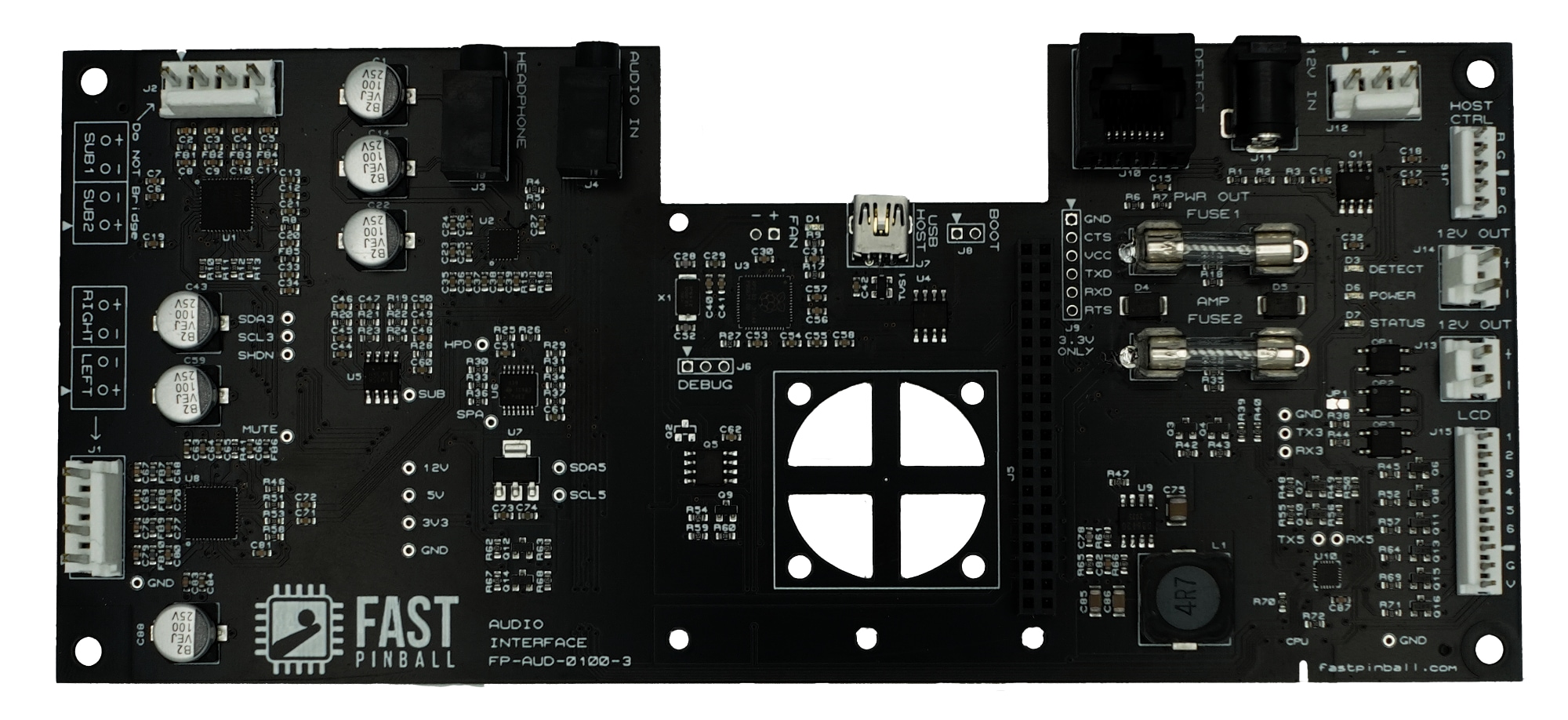
The FAST audio interface board offers a fully integrated pinball sound system along with several other features that normally require multiple boards. The key components include: software controlled amplifiers, automatic power handling, headphone management, LCD display control, and a system watchdog. The audio interface board offers a much simpler wiring interface, especially if mounted on the back of the speaker panel. In this case only a few wires are needed to go back into the backbox. If a Raspberry Pi is used as the main game computer, wiring is even more simple as it can be seated directly into the audio board.
The FAST Audio Interface was designed to easily integrate with other FAST controllers and hardware.
Features
- Three stereo amplifiers, for main, subwoofer, and headphones.
- The amps are Maxim MAX9744. (data sheet PDF)
- ~15 watts usable output power (RMS) per channel.
- Separate volume controls for the main speakers, subwoofer, and headphones.
- All settings (volume, levels, headphone plug-in behavior, etc.) are controlled by software via the standard FAST Serial Protocol (virtual serial commands over USB). (No more opening the backbox to change the volume or bass levels!)
- Designed for use with 4Ω speakers
- The subwoofer amp has a built-in low pass filter & crossover.
- All frequencies are sent to the main speakers & headphone jack.
- Subwoofer cutoff is 120Hz.
- Headphone detection with software configurable behavior, options include:
- Automatically switch to headphone output when a headphone is plugged in
- Automatically switch back to main speakers when headphones are removed
- Disable headphone detection
- Headphone detection is done via impedance detection, so it works with any 3.5mm stereo jack and will also work with an extension cable to the front of the machine.
- The headphone output can be configured for line level, perfect for recording your machine's audio for streaming or video recording with perfect pinball sound.
- Interface to send commands to control the machine's LCD panel settings
- A header is included to connect your LCD display's control panel to the audio interface board.
- This allows you to control the LCD panel's brightness, contrast, input settings, and other settings via software.
- PC and Raspberry Pi power and reset management.
- Pinball main “power on” detector.
- The audio interface board can detect when the pinball machine is powered on.
- This allows the audio interface board to automatically turn on the Raspberry Pi and other FAST controllers when the pinball machine is powered on.
- This also allows the audio interface board to automatically turn off the Raspberry Pi and other FAST controllers when the pinball machine is powered off.
- 12V power distribution headers for external loads (LCD screen, etc.)
- Built-in system watchdog
- Volume levels restored during power on initialization
- Raspberry Pi fan driver
- On board power supply for Raspberry Pi and amplifier drivers
- Single 12V power input
Connector Housings Needed
| Qty | Pins | Size | Description |
|---|---|---|---|
| 2 | 4-pin | 0.156" | main speakers, subwoofer |
| 1 | 3-pin | 0.156" | 12V power in |
| 2 | 2-pin | 0.156" | 12V power out |
| 1 | 5-pin | 0.100" | host PC control |
| 1 | 9-pin | 0.100" | LCD control |
Wiring
FULL WIRING GUIDE 🤩
If you're using this FAST Audio Interface in your machine, be sure to check out our full wiring guide which details everything you need to know about every connection on this board.
Main Speakers
- Main Left Channel Positive Output
- Main Left Channel Negative Output
- Main Right Channel Negative Output
- Main Right Channel Positive Output
(Do not Bridge Main Speaker Outputs)
Subwoofer Outputs
- Subwoofer 2 Positive Output
- Subwoofer 2 Negative Output
- Subwoofer 1 Negative Output
- Subwoofer 1 Positive Output
(Do not Bridge Subwoofer Outputs)
The subwoofer outputs are not stereo. The left and right channels are combined, the low-pass filter and slope is applied, and then identical signals are sent to the subwoofer outputs. You cannot bridge the subwoofer outputs, instead we recommend a single subwoofer with a dual voice coil.
Headphone / Line Out jack
3.5mm Stereo jack
- Tip = Left Channel Output
- Ring = Right Channel Output
- Sleeve = Ground
This jack can be used for headphones, or configured as a line-level output for use with an external amp or recording equipment. (Settable via software.)
When configured for headphone use, the FAST Audio Interface uses impedance detection to determine if a headphone is plugged in. This means that the headphone detection will work if you run an extension to the front of your machine. If you're building your own extension, you don't need a jack with tip or ring switches since they're not used. A standard 3.5mm stereo jack will work fine.
Audio In
3.5mm Stereo jack
- Tip = Left Channel Input
- Ring = Right Channel Input
- Sleeve = Ground
Only one stereo input is used, which is distributed to all three amps.
PC Control
- Reset Open Drain Output
- Ground
- Key
- Power Open Drain Output
- Ground
Host USB
- Right Angle USB Mini B
Detect Connection
Right-angle RJ-45 jack. Connect to the FAST controller EXP or DSP bus. This is only used to detect system power.
- Not Connected
- Detect Negative
- Detect Positive
- Not Connected
- Not Connected
- Detect Positive
- Detect Negative
- Not Connected
12V Input
There are two jacks for power input, one is a 2.1mm barrel jack, the other is a 0.156” two pin header. The center pin of the barrel jack is positive. Both of these connectors are electrically tied together. The positive and negative of the 0.156” connector are noted by + (positive) and - (negative) next to the connector. This input should have an upstream power supply or fuse rated for no more than 5 Amps.
12V Outputs
There are two jacks for power output, both 0.156” two pin headers. Both of these connectors are electrically tied together. The positive and negative of the 0.156” connector are noted by + (positive) and - (negative) next to the connector. Both of these outputs are switched on by system power and can be held on by the audio controller to allow for safe system shutdown. These outputs are also fused by “PWR OUT” Fuse 1 (5x20mm). Fuse selection needs to be made based on load requirements. However, the selected fuse should be no higher than 3 Amps.
LCD Control
This interface connects the LCD control switches to allow software control of various features that are part of the display hardware. It can also be used to fix issues such as a display that powers up disabled. This LCD control connector is attached to the switch panel that normally comes with the display interface. It should work with any switch panel that uses common grounded switches. If a switch matrix is used for the display control, or a non-common ground approach is used, extra hardware will be necessary between the audio board and the display interface.
- Switch pin 1 control
- Switch pin 2 control
- Switch pin 3 control
- Switch pin 4 control
- Switch pin 5 control
- Switch pin 6 control
- Key
- Ground
- 5V Output. This 5V output is intended to control extra hardware if needed to control the display interface. (Do not use it for any other purpose. It should be limited to 50mA maximum to manage overall system power.)
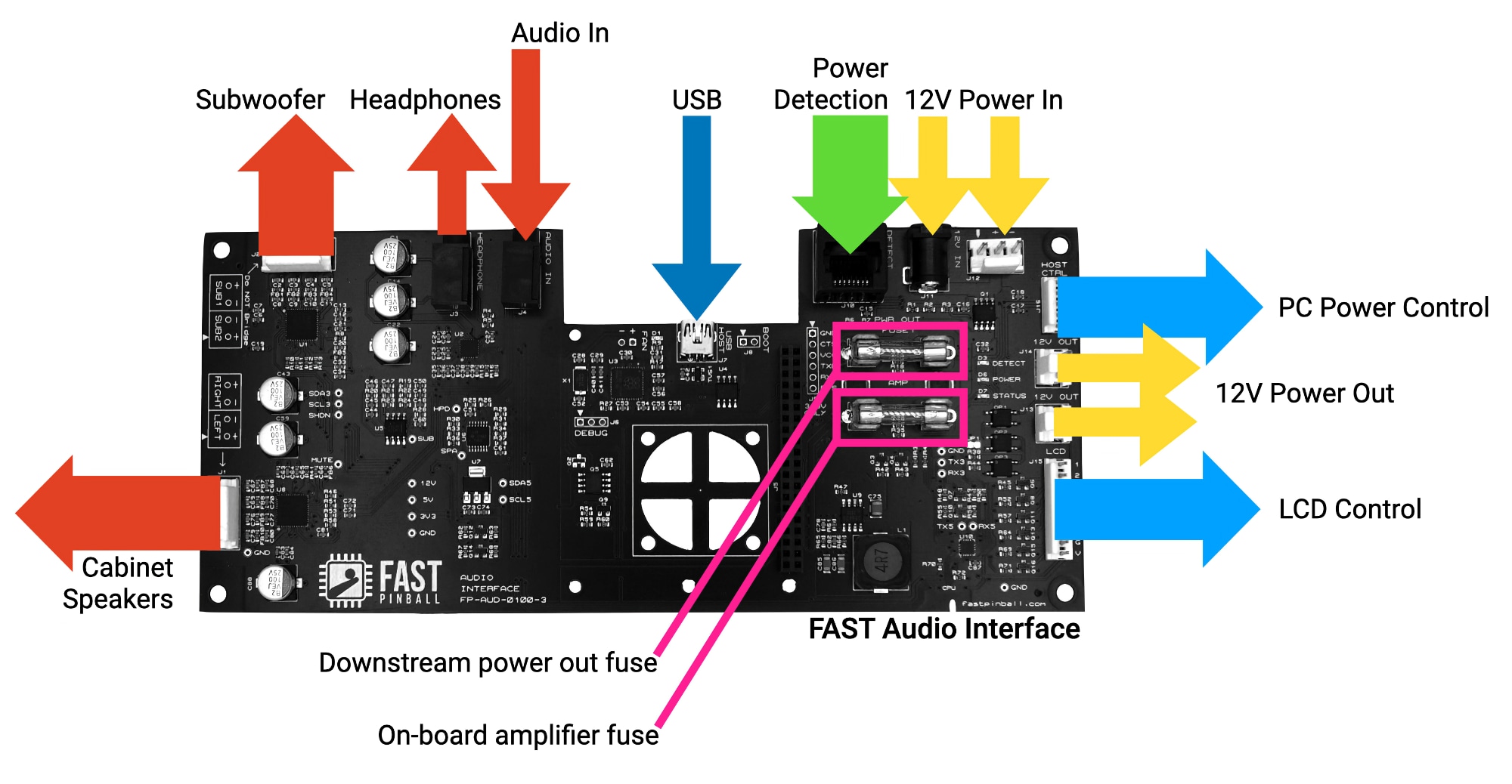
Fuses
The FAST Audio Interface board has two fuses. Both are 5x20mm.
- Fuse 1 (labeled
PWR OUT) protects the two 12V outputs (J13andJ14). 3 amps max. - Fuse 2 (labeled
AMP) protects the on-board audio amplifiers. 2.5 amps should be used if speaker outputs are not fully loaded (only 2 or 3 speakers). If both subwoofer outputs are used, a 3 amp fuse may be necessary.
Raspberry Pi Integration

A Raspberry Pi can be mounted to the audio interface board as shown in the diagram above. This is optional.
The use case for this is for FAST Retro Platform games with a FAST Retro controller replacing the original MPU and this audio interface board replacing the original audio board. In this case, the Raspberry Pi attached to the audio interface can drive the "2.0" game code (with the "1.0" original game code coming from the FAST Retro Controller.) See the documentation on the FAST Retro Platform for details.
Serial Interface
The FAST Audio Interface Board has an onboard microprocessor which connects to a controlling computer via the FAST Serial Protocol via USB or a serial control pin. When you connect to the controller via USB, a new virtual serial port appears. (This is automatic, no drivers are needed.)
The serial port function as follows:
| Port | Processor | Description | Baud |
|---|---|---|---|
| Port 1 | AUD | FAST Audio Processor | 230400 |
Baud rate is 230400!
The FAST Audio Interface serial connection is 230400, not 921600 as the main controllers. If you don't get any serial response, or garbage characters, it's probably because you're connecting at the wrong speed. :)
The exact name or number of this port will depend on your specific computer. (For example, on Windows it will be named something like COM3 or COM7. On Mac it will be like usbserial41xxx.)
The controlling PC communicates with the microprocessor by making a virtual serial port connection and then using the FAST Serial Protocol to send and receive commands and status messages. (Most of these as ASCII, meaning you can interact with your pinball machine audio interface via a terminal emulator!)
Always On Power Jumper

The FAST Audio Interface uses its RJ-45 jack, connected to either the EXP or DSP bus, to turn itself on and off by detecting the power state of the controller on the other end of that bus. This is useful in retro machines where the audio interface is connected to "always on" power, since this feature allows the board to turn off when the machine is off.
If you don't need this (like if you're using this audio interface in a modern machine), you can disable the auto power detection by dropping a dab of solder onto JP1. (This is a solder bridge jumper. Just solder it closed to set it.)
Note that the “power detect” serial command will still report correctly even with the jumper installed.
Mechanical Diagram
All dimensions are in inches.

Electrical
- 12V input maximum current: 5 amps (combined both connectors)
- 12V outputs combined: 3 amps (Fused by FUSE 1, 5x20mm)
- PC control outputs (reset, power) each output 150mA max (open drain)
- LCD control interface (6 outputs) each output 150mA max (open drain)
- All speakers outputs (main and subwoofer) are designed to drive 4 ohm loads
- Amplifier fuse (Fuse 2, 5x20mm) should be no more than 3 amps. 2.5 Amps should be used if speaker outputs are not fully loaded (only 2 or 3 speakers). If both subwoofer outputs are used, a 3 amp fuse may be necessary.
Errata
Right and left audio may be swapped on the audio input and headphone jacks due to part shortages. Final release should have everything labeled based on available connectors. Swap left and right speaker outputs to fix if swapped. As long as the headphone and line input jacks match they will be correct.
N or > jump the next page, P or < for previous, search with S or ?