Understanding fuses and current draw in a FAST Neuron-controlled pinball machine
Wiring, high voltage, and electricity can be dangerous. Read this first!
The voltages and electricity discussed here can be dangerous and could cause property loss or death. It is your responsibility to ensure you are aware of these risks and comfortable with these processes. Furthermore your local jurisdiction may have regulations or rules which differ from what we discuss here, including wiring colors, standards, techniques, etc. Although based on broadly adopted methods, FAST Pinball does not employ Professional Engineers and this information is not professional recommendations. There may be errors, omissions, or typos here. Any pinball machine available to the general public should be reviewed by a licensed Professional Engineer in your region. Use this content at your own risk.
You probably know that pinball machines have lots of fuses, and that it's annoying when they blow. Now that you're actually building a pinball machine, you need to understand them for real. The whole purpose of a fuse is that it's a 5-cent thing that blows to prevent something much more expensive from being destroyed. (The first time you blow a fuse and realize it just saved your $159 I/O board is worthy of a pinball maker badge!)
This guide will explain how fusing works in your pinball machine, and will provide some guidance on the types and current ratings of fuses you should use. Fuses are sized and rated based on current (amps), which is something we've been casually tossing around in the guides up until this point. So let's take a step back and look at what you need to know about current and amps as you wire up your machine.
Understanding voltage, amps, and watts
There are a million learning sources on the internet which can give you the basics of voltages, amps, and watts. So if you're new to this, do some homework there.
We briefly mentioned this in our guide to pinball wiring standards, the most important thing to know for pinball wiring is wire gauge and fuses are based on amps, and more amps require thicker wires.
In other words, voltage has nothing to do with wire gauge. a 22-gauge wire could have 10 or 100 or 1000 volts going through it, as long as the amps were within the wire's rating.
Knowing that there's no linkage between volts and wire gauge is most important when thinking about your machine's 12-volt circuits. When you add up the current ratings of everything in your machine that runs on 12V, you might find the total which is over 7A, the maximum amp rating of a 0.156" connector pin on FAST boards. This is easy to handle (as we'll show here), but the point is that even that "low voltage" 12V can easily exceed the current ratings of a single wire!
Each component supports different amps
Another important thing to know about current and fusing is that when you're looking at the max current rating for something, you have to think about the entire circuit, not just the part you're looking at.
For example, you might think "how much current can my wire support?" That's a good starting point, but you need to also think about what the wire is plugged into? How much current can it support? And what about the actual connectors themselves? How much current can they support?
The following diagram shows the complete chain from a 12V power supply to the smart power filter board, and how there are actually 5(!) pieces involved—each with a different current rating!
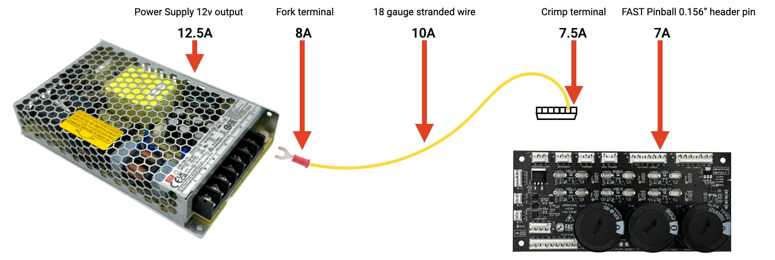
Based on the diagram above, the lowest-rated item in the chain is 7A, so that means that whole chain shouldn't go above 7A. And how do you ensure that? With a fuse!
You can also flip it around and look at it from the other way. That power supply in the diagram above can deliver 12.5A. But that's higher than anything else in the chain can support. So how do you ensure that the power supply can't shove its full 12.5A down the chain, potentially heating, melting, and/or destroying all the lesser-rated pieces along the way? With a fuse!
If you didn't have a fuse between the power path in the diagram above and all your components, then your components could draw more and more power, even going over 7A. (After all, that power supply is good for up to 12.5A!) But by then, you're melting your terminals and wire.
You might think, "No prob, I'll just make sure I don't add more devices that combined to more than 7A." That's a good plan! But it doesn't protect against the other issue, which is a short. If a wire from the 12V side of the circuit touches a ground wire (broken solder joint, loose connector, etc), then that PSU will instantly have a high-current, low-resistance path to ground, and it will output its maximum 12.5A, again cooking your wire.
Of course this won't happen in your machine because you're going to fuse everything properly!
Understanding fuses
So, the strategy is to put fuses in your circuits as strategic and purposeful failure points, hoping they fail before something more expensive does. But how do fuses actually fail? If you have a fuse rated for 5A, and the circuit gets 5.5A for a second. Does it fail? What if it's for a minute instead of a second? Or what if it's 10A for a second?
All fuses are both current and time sensitive. They fail when some amount of overcurrent has flowed for some period of time. Fuses can roughly be divided into "slow blow" and "fast blow" types, which have different profiles for how they blow. (Here's more information on slow-blow versus fast-blow fuses.)
Most fuses in pinball machines are the "slow blow" (Often etched into the fuse as S.B.), so this means that overloading them for a period of time is generally fine. (As just one example, when the power windings of your flippers are active, that's almost a dead short which could be over 20A for a few tens of milliseconds. Your fuse has to "survive" this, but still blow for something that lasts longer.)
This time delay before a fuse blows is something you need to consider when sizing your fuses. Going back up to that 12V circuit example from above, if you have a circuit with a max current rating of 7A, then you can't use a 7A fuse to protect it, since the fuse will be able to go over 7A for awhile. You want the fuse to be the single weakest part of the circuit, not tied with the device you're trying to protect!
Fusing and fuse selection is one of the topics that's difficult to provide generic guidance on since there are so many things to take into consideration in your specific machine. The most important thing is to TEST, TEST, TEST! All fused circuits should be tested. You can use your meter to check what the actual current draw is during typical and maximal (everything full on and loud) scenarios. You can also test for shorts. (Literally touch the V+ wire to ground and make sure the fuse blows.)
When figuring out your fuse values, start with lower current fuses and work your way up. If you think a circuit needs a 4A fuse, start with 2A. Maybe it blows right away, fine, move up to 2.5A. Hey, that one made it farther, but still failed in a busy game mode. Fine, try a 3A fuse. And... hey! Maybe 3A works and you don't need to go to 4A. Yay!
Why the excitement? The lower your fuse values are, the greater chance they blow first. Lower is better! Your main goal for fuse sizing is when an ULS occurs ("unexpected light show", something that will happen a lot when building your machine), you want that sound and flash to be a 5-cent fuse, not your audio board.
Understanding FAST Modern power circuits
In the FAST Modern Platform, the smart power filter board you wired up a couple of guides ago is where most of your machine's fuses are. (Another reason why this board is on the outside of your power box!) This filter board is also the place where the main trunk power circuits from the power supplies are split into multiple branch circuits.
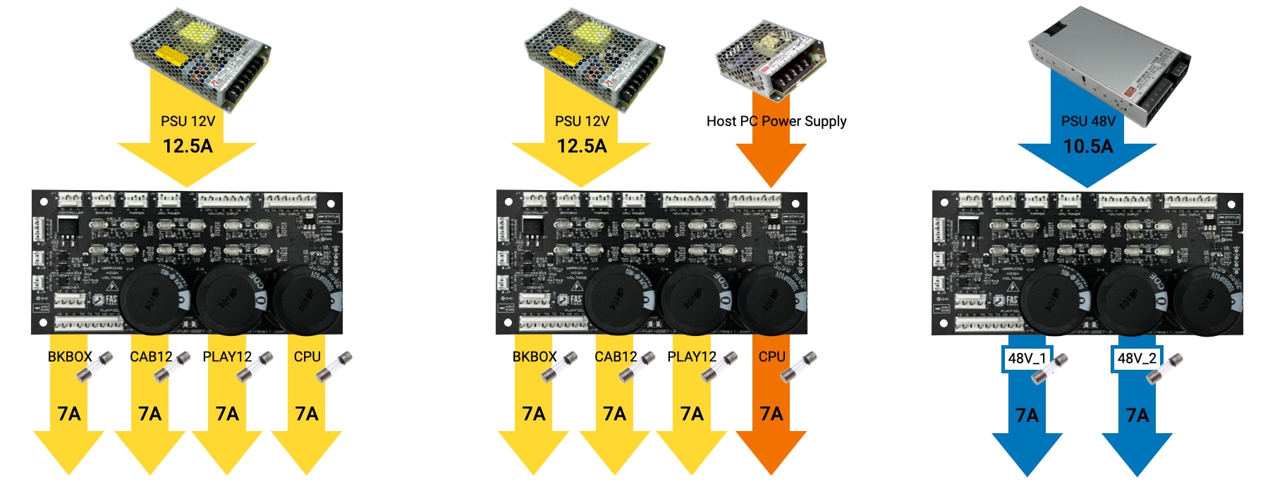
The diagrams below show the various DC inputs from the power supply, broken out into the branch circuits (one per fuse). The left one is how it works with 12V going to the CPU branch circuit (J5 pins 1-2 on the filter board), whereas the center diagram shows how it works when you have a different voltage power supply for your host PC. The diagram on the right shows the two branch circuits for the 48V.
A few things to note:
The circuit / fuse names do night align 1-to-1 with the power output headers on the filter board. For example, the filter board outputs for CONTROLLER, BACKBOX, and TOPPER are all on the same circuit and all protected by Fuse F2 labeled BKBOX. Further, the single 48V input is split into two circuits, 48V_1 and 48V_2, with both of these circuits going to the playfield via the output header PLAYFIELD, while the output header CABINET only gets the 48V_2 circuit.
Each of these circuits requires different types of planning, so we'll walk through them each separately.
Planning your 12V circuits
You might notice in the power circuit diagrams above that the max current ratings of the branch circuits add up to be higher than the power supply's maximum output. This is true. The current rates for each branch circuit are the max for that circuit only, while the rating for the power supply is the max that supply can support.
So what happens if multiple branch circuits, all within their allowable range, combine to attempt to draw more current than the power supply can support? The power supply will enter its overcurrent failure mode, and you'll have to read your power supply's data sheet to find out what yours does. (Power supply failure modes are covered in our guide to choosing pinball machine power supplies.)
Remember from the earlier part of this guide that every component in the circuit needs to support the levels of current being used. So as we've mentioned previously, FAST boards with 0.156" headers are rated for a maximum of 7A per pin. If you have a 12V power supply that can provide more than 7A, then you need to spread the load across multiple parallel wires to ensure that each wire doesn't get more than it can take.
This is why we connected two sets of 12V wires from the power supply to the filter board input back in that guide. For example, the 12V supply we recommend is rated for a max of 12.5A, meaning running two sets of wires ensures that each wire (and therefore each pin on the FAST board) is getting a max if 6.25A.
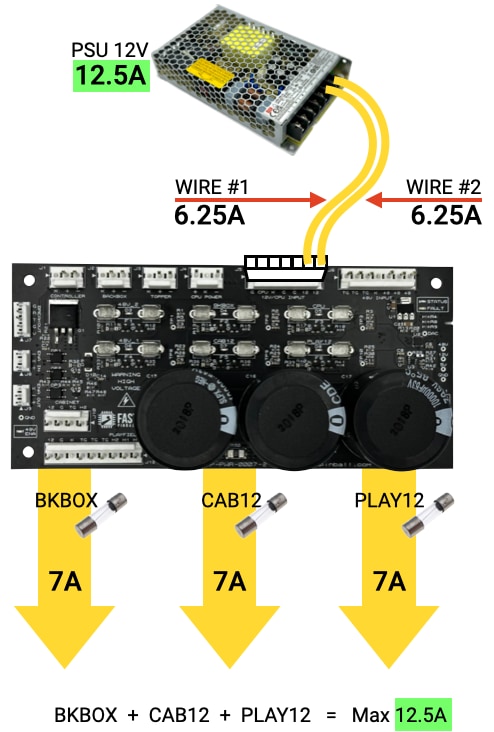
So this diagram above represents what we recommend. Each branch circuit can be up to 7A (well, say 6A to allow for the slow blow fuse headroom), but all three combined can't be more than 12.5A since that's the power supply's limit. (Note that the black ground wires are not shown, but they should always be the same quantity and type as the V+ wires.)
What if you want more 12V power available? You can always add in the CPU circuit to that too, and then go up to a power supply with more current, like this:
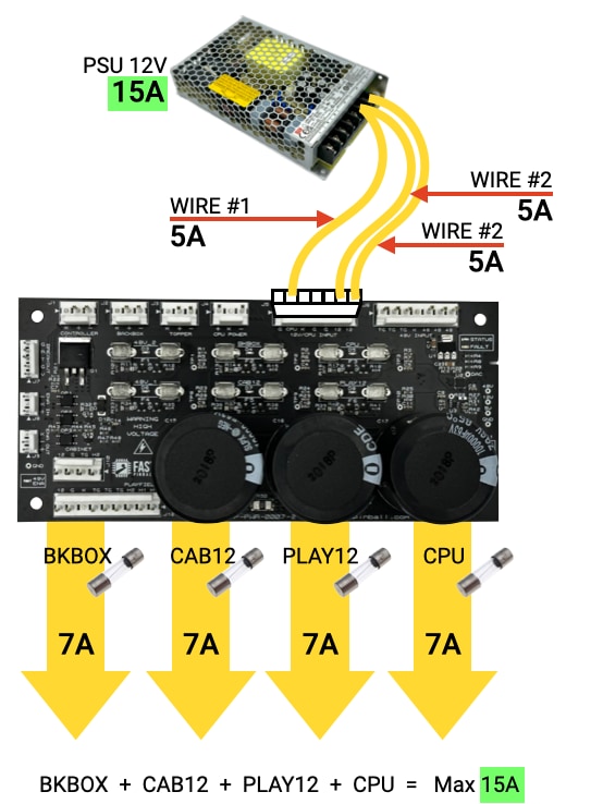
The diagram above shows a 15A supply with 3 wires, meaning each wire (and pin) will only have to carry 5A max. And now you have 4 branch circuits available, which again can be up to 7A each but can't be more than 15A combined.
Again, the key is to ensure you don't exceed the limit of any one component in the circuit. You would not want to use a 25A power supply with only 3 wires/pins since those are 7A max / 21A combined, so a 25A power supply would not be safe since it can provide more power than the circuits can safely pass.
Be careful when parallel lines are run
In these examples where multiple parallel wires are being used support larger loads, what happens if a wire comes loose? If you have a 12.5A load going over two wires that's suddenly reduced to one wire, no fuse would blow since the fuses on the filter board are after the branch circuit split. You would end up with the full 12.5A on a single wire going into a single pin, and who knows exactly what would happen then?
Luckily the wire runs between your power supplies and filter board are short, and the likelihood of one of those wires randomly failing or coming undone is pretty slim. Still, if you wanted to be extra safe, you could get 5x20mm inline fuse holders from Amazon for about $2 each and install those into your V+ wires with 6A fuses and never have to worry about it.
12V Audio Interface fuses
Since 12V is used for so many things in a FAST modern pinball machine, you will most likely end up with some branch circuits being divided into even more sub-circuits.
For example, the FAST Audio Interface has two 5x20mm fuses. Fuse 1 is labeled PWR OUT and Fuse 2 is AMP.
The AMP fuse is used to protect the amps on the audio board itself. (There are three, one for the main speakers, one for the subwoofer, and one for the headphones.) This fuse value will most likely be 2-3A, depending on what speakers you choose.
The Audio Interface also has two 12V output headers (J13 and J14) which you can use to power further downstream things, like a display or some other 12V device(s) in your backbox. Those two headers are protected by the PWR OUT fuse, and you would calculate the sub-circuit load and fuse size just like the main 12V circuits.
So, how do you actually figure out those loads?
Calculating 12V circuit load
We've shown how the FAST Smart Power Filter Board has three 12V circuits (or maybe four if you're using the CPU circuit for 12V too). We've also shown that each of these circuits can support up to 7A, which means you can use a fuse up to 6A. But remember, you want to use the lowest value fuse possible. So how do you figure out what that is?
Option 1: Experiment!
Honestly the easiest way to do this is something we touched on already: just buy a variety pack of fuses, start with the smallest value in your kit and then keep on increasing the value (step by step) until you find the lowest value fuse that doesn't blow under ordinary conditions. (Again you will want to purposefully try shorting out each circuit in various locations to test and verify that the fuse does blow.)
The only caveat to using this method is you need to ensure that you don't exceed the current rating for the specific branch circuit. In other words, if you get all the way up to a 6A fuse and it continues to blow, it's time to look at the things that are on that 12V circuit and see if you can move some things to a different 12V circuit.
Option 2: Math
The other option you can use when designing your 12V circuits is to figure out which devices will be attached to each circuit, look up (or test) for their current draw ratings, and then try to pick the right fuse value. Doing this will still require the experimentation as described above to dial-in the exact fuse value. Really all you're doing with this math is a quick "gut check" to make sure you're not planning for 10A on a single circuit, for example!
Here's an example list of the various things that might connect to each 12V circuit:
Backbox 12V circuit
- Neuron Controller (and the I/O Loop)
- Backbox LEDs attached to the Neuron (see 12V current conversion note below)
- Topper (LEDs? Servos?)
- Display (LCD, DMD, Segments?)
- Audio Interface (Amps + speakers)
Cabinet 12V circuit
- Cabinet LEDs (under cabinet, stadium lighting?)
- Shaker motor
- Coin door / bill validator
- Other switch / button LEDs?
Playfield 12V circuit
- LEDs
- Servos
- Playfield / Apron LCD(s)?
- Optos
Convert all device ratings to 12V equivalents!
Remember that current draw varies based on voltage, so when you do your math for our 12V circuits, you need to convert the current draw of any devices the equivalent current they'll draw at 12V.
For example, LEDs connected to FAST expansion boards run on 5V. (The expansion board generates the 5V it needs from its 12V power input.) If you look up the specs of the WS2812 LEDs your using, you might see they can draw 50mA each when they're at their full white, max brightness. So if you have 100 LEDs, that's about 5A total. (That's a lot just for 100 LEDs!)
But that's 5A at 5 volts. To figure out how much that would be at 12 volts, you do some quick math:
5 (amps) ✕ 5 (volts) ÷ 12 (volts) ≈ 2
So 5A at 5 volts is only 2A at 12V. Not bad for 100 LEDs!
Real world variation and usage patterns
The other thing you need to think about is that not all your devices will use their max current at all times. For example, RBG LEDs are really, REALLY bright. To most peoples' eyes, there's no different between LEDs at 80% power (CCCCCC) and 100% power (FFFFFF). But from the electrical point of view, 80% power means 20% less current draw than 100.
You might also find that your actual devices don't consume as much current in the real world versus what their data sheet says. We recently tested an LCD display whose spec sheet said it required 2A (@12V), yet in our testing with a meter, we couldn't get this thing to take any more than 0.4A (400mA), even on full brightness! Most likely what happens is a sort of "baker's dozen" situation, where device manufactures want to err on the side of caution, so they overstate their actual current requirements.
Another example of this is with RGB LEDs. We got one batch that supposedly consumed 50mA with all channels at 100%, but from our testing, they only consumed 31mA at FFFFFF! So again, this is why the real world testing and experimentation is needed even if you love math and have a lot of data sheets.
It's perfectly acceptable to plan for the devices on your 12V circuits to not run at full power. For example, if all the LEDs in your system could theoretically consume 5A @12V, but you plan to run them at 80% power max and you don't expect that all of them will be all on at full power at the same time, you might plan for only 3A or 4A of LED power consumption. This is fine! If you're wondering if this is dangerous, like, "What if some user turns them up with too much power?", that's still safe because that will just blow a fuse (as intended) if the total draw gets too high.
CPU (Host PC) Circuit
As mentioned already, the Host PC circuit (which is called "CPU" on the smart power filter board) is its own completely-isolated circuit. It has its own power input pin, its own fuse, and its own output.
Like every 0.156" header pin in the FAST Pinball ecosystem, this CPU circuit is limited to 7A max (which means you should not use a fuse higher than 6A).
You can use just about any voltage here (from maybe 6VDC up to 60VDC?). Most people try to get a host PC that runs on 12V so you can just use this circuit as another general 12V circuit.
Or, if you have some strange device that requires a one-off voltage (24V super toy? or?), then you can get a host PC that runs on 12V and power it from one of the three headers powered from the backbox 12V circuit, and then repurpose the CPU 24V circuit for your unique device. (You must use DC power though. If you have some device that requires AC, you cannot connect the AC through the FAST Smart Power Filter Board.)
Host PCs have the same "real world" variation as other devices. One small form factor PC we looked at required 5A @12V according to its data sheet. But when we received it, it shipped with a 4A power supply. And then we did some testing, including running it in the configuration we'll use in the final pinball machine, and we ran system benchmarking software on it to run the CPU and GPU at 100% max, and even during those tests, this PC only consumed 2.5A @12V. This is fine, of course, it just meant that we selected a 3A fuse instead of a 5A fuse, and we knew we had plenty of 12V headroom for other things.
48V Circuits
Now that you've got your 12V circuits planned, lets move on the 48V circuits. While the basic electrical concepts are the same (branch circuits, fuses, current limits in wiring, etc.), the way the 48V circuits are used in pinball machines are pretty different than the 12V circuits.
So let's first dig into how the 48V circuits behave in a pinball machine, and then we'll look at the practical guidance for how you should design yours.
Why are the 48V circuits so different from the 12V ones?
We touched on this in our guide to selecting pinball power supplies, but it's important enough to reiterate here.
When compared to the 48V circuits, the 12V circuits in your machine are more gentle and stable. Sure, turning on all the LEDs at once, with full music cranking, and the shaker motor running, will require more power than when the machine is idle. But even during attract mode, the 12V is still being used for the displays, light shows, the host PC, the FAST boards, etc. So the different between the "baseline" and "max" 12V current needs are not too extreme. For example, your 12V circuits might require 40% of their capacity when the machine is idle, and 60% when the machine is busy, but they never really operate outside of that range, and they never spike.
Compare that to the 48V circuit. When no coils are active, the 48V circuit is using 0 amps. Literally nothing at all. Then when you fire a powerful coil (like a flipper power winding), the 48V current will spike crazily high, like 20-30A. This is way over your sustained current ratings for the 48V circuit, but it's ok since this massive current is only required for a few tens of milliseconds at a time. So your 48V circuits, require 0% power for 99.999% of the time, but for that 0.001% of the time it's like "OMG I NEED 300% POWER CAPACITY RIGHT NOW GO GO GO GO GO!!!" and then 15ms later it's back to "zzzzz" 0% again.
The FAST Pinball modern platform, and smart power filter board, have been designed with these differences in mind. For example:
How those 3 huge capacitors help the 48V circuit
The FAST Smart Power Filter Board has three huge capacitors, 10,000µF each, attached to the 48V circuits. (Both 48V circuits share access to those capacitors.)
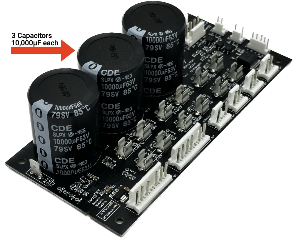
A capacitor is a device which stores electrical energy. It's essentially a reserve holding tank which stores electrons which can be used when the circuit needs more power. The reason these capacitor / holding tanks exist for the 48V circuits might be clear to you based on what we've covered so far: A strong solenoid's power winding requires 20A or 30A of power for the few milliseconds it's active, but your 48V power supply is only rated for 10.5A and therefore can only deliver a max of 10.5A. So where does the rest of that power come from? The 30,000µF capacitance from the power filter board!
Recall from the guide to grounding that the resistance in the wires, connectors, and coils in your 48V circuits means that when a powerful coil fires, the 48V power supply will quickly hit its maximum current output which causes it to start dropping its voltage output in order to maintain the full 10.5A of current. (This is why it's important to select a 48V power supply with "constant current" overcurrent behavior)
So your power supply is going to drop the voltage it's delivering, and the resistance in your wires is going to drop the voltage even more (due to Ohm's Law), meaning that the powered solenoids would receive less than 48V and feel weak. To mitigate this, those capacitors dump some of their reserves into the circuit, raising the voltage back to 48V for full flipper power.
Those capacitors are constantly charging and discharging as games are being played, and they should provide enough capacity for four flippers in a busy machine.
These capacitors will hold their charge after power is removed
Since capacitors are used to store electrical energy, they will hold their charge after power is removed. The FAST Smart Power Filter board has circuitry which will discharge these capacitors once power is removed, but this happens slowly over several hours. Always treat large caps as if they're charged!
48V parallel supply wires
Back in the guide to smart power filter board wiring, we showed you how to run 3 sets of parallel 48V supply wires from the power supply to the filter board, and also from the filter board to the playfield interchange board.
So even though your 48V power supply is only rated for 10.5A, you can see that once you add the capacitors into the mix, the 48V circuit can go well over 10.5A. This, combined with how important minimizing resistance is to address voltage drop on the 48V circuit, is why having multiple wires is so important and not optional.
Splitting loads between the two 48V branch circuits
The three 48V sets of wires from the power supply to the filter board are divided into two 48V branch circuits, with fancy names "1" and "2". The following chart shows how each circuit is used in the filter board:
| Name | Fuse | Output Header Pin Labels | Output Headers |
|---|---|---|---|
| 1 | 48V_1 | H1 | Playfield (2) |
| 2 | 48V_2 | H2 | Playfield (1), Cabinet (1) |
You now need to decide which circuits you use for what. (We'll refer to these at H1 and H2 for now. "H" just means "high voltage".)
First, notice that the playfield has access to both circuits. It has two wires for H1 and one for H2. This means that H1 should be your "primary" playfield 48V power which you use for most things. H2 can be used for secondary things.
How should you divide these? It depends on your machine. If you have more than three flippers, maybe you put the two flippers on one circuit and the others on another? Or if you have magnets, you might want to put the magnets on H2 and everything else on H1.
The filter board power output header for the cabinet only has access to the H2 circuit. That's fine, since the cabinet won't have much need for 48V. Most likely it's just a knocker, which a lot of people don't even use anyway. (Some shaker motors are powered by 48V too, though it seems those are being phased out for 12V ones nowadays.)
Part of this decision about what devices you connect to which 48V circuits could be based on trying to keep your machine functional if the H2 48V fuses blows. For example, if you just have magnets and the knocker on H2, then technically your machine is still playable even that fuse blows, which might be nice.
The specifics of coil, solenoid, magnet, and shaker motor wiring are covered in future guides, so read those before you make any specific wiring decisions.
Ground lines
Most of the drawings and conversation in this guide have just talked about "power circuits" and "numbers of lines" without actually showing or mentioning ground return lines. The specifics of how these are used and run are covered in other guides, but there are a few important things to keep in mind about your 48V and 12V grounds.
First, the 12V ground and 48V ground should NEVER connect to each other in your machine. Never, never, never. The reason for this has been discussed already, that you don't want the wild swings of the 48V toxic ground rise to mess with the 12V devices.
These two DC grounds are connected together inside the smart power filter board, which connects them in a way that protects the 12V ground from the 48V toxic ground. If you connect them together anywhere else, you will most likely damage something on your 12V circuits.
The second important thing about grounds is that you must ALWAYS run the same number of ground wires as you have V+ wires. So when you see two 48V supply lines running to a board, you will also need two toxic ground returns. (Or three and three, etc.) Make sure the counts always match!
AC line fuse
There's one more fuse value to consider, and that's your AC line fuse which is installed into your power box. We discussed the specific wiring of this fuse in the AC line input wiring guide, as well as the suggested values.
If you're in a 120V country, 8A should be fine. 240V countries should use a 5A fuse. (Again, since total power delivered is based on current and voltage, that allows for 960W total watts for 120V and 1200W for 240V.)
These should be plenty. The two power supplies we recommend are 500W max for the 48V and 150W max for the 12V, so you shouldn't be anywhere close to those limits and in fact could probably use lower-value fuses. The main thing this line fuse protects is a dead short, which should hopefully blow a fuse of any allowable value.
And again, ensure that your entire AC circuit chain: the line cord, input socket, wire, connectors, etc. all can support the amperage rating of the fuse you select. As always, you want the fuse to the weakest part of the circuit and you want it to fail first.
Key takeaways
A lot of important concepts were covered in this guide, and it's probably worth reading through a few times to make sure you understand everything. Here are the most important takeaways about fusing, current, and power circuits for pinball machines:
- The fuse should be the weakest part of a circuit.
- All fuses will allow more current than they're rated for, for a short period of time.
- This means the fuse rating needs to be lower than the next-lowest rated component in the circuit you're trying to protect or the fuse might never blow.
- You want to use the lowest value fuse possible in each circuit. Lower is better!
- Test your circuits with progressively higher-value fuses to figure out the minimum fuse value you can use.
- Make sure you can blow a fuse. You need to confirm the fuse will blow when and how you expect.
- Never "solve" a frequently blowing fuse by just adding a higher value fuse without ensuring everything else in the circuit, and things upstream and downstream, can support the new value.
- It is impossible to provide concrete guidance without knowing the details of your machine. You are responsible for your own machine's safety!
Wow, that's a lot! But by this point, you have all the base wiring and power circuits complete, and now you can start the actual fun parts of wiring up the more pinball-related pieces of your machine. Yay!
N or > jump the next page, P or < for previous, search with S or ?