Ground wiring guide for FAST Neuron-controlled pinball machines
Wiring, high voltage, and electricity can be dangerous. Read this first!
The voltages and electricity discussed here can be dangerous and could cause property loss or death. It is your responsibility to ensure you are aware of these risks and comfortable with these processes. Furthermore your local jurisdiction may have regulations or rules which differ from what we discuss here, including wiring colors, standards, techniques, etc. Although based on broadly adopted methods, FAST Pinball does not employ Professional Engineers and this information is not professional recommendations. There may be errors, omissions, or typos here. Any pinball machine available to the general public should be reviewed by a licensed Professional Engineer in your region. Use this content at your own risk.
This guide walks you through proper ground wiring for your pinball machine. Recall from our intro guide "Understanding ground lines and grounding in a pinball machine" that there are multiple different types of "grounds" in a pinball machine, specifically:
- Earth Ground
- Chassis Ground
- DC Clean Ground
- DC Toxic Ground
In this guide, we'll first discuss what each of these grounds are and how to handle them, and then we'll look at how/when/if they're all tied together.
Earth ground
Earth ground is literally an electrical connection to the physical ground of planet Earth. In your house, it's the third prong of an AC plug, and in your walls this is connected to a copper rod or pipe which goes into the ground.
Your pinball machine is connected to earth ground via the green wire connecting your power supplies to the line cord plug from AC line input wiring guide. But before we get too far, why is earth ground important?
It's a safety issue. All metallic parts of a pinball machine must be connected to earth ground. In fact, this is so important that pinball show organizers test for it! It's a simple test, just unplug your machine and set your meter to continuity mode, touch one probe to the ground pin on the machine's power cord, and then use the other probe to touch any metal part--the lockdown bar, legs, hinges, coin door, etc. You should get the continuity beep, and if you don't, that means that metal part is not connected to earth ground and the machine will not be allowed on the show floor.
Connecting all the metal parts of your machine to earth ground provides safety because any short or broken wire on the inside that touches a metal part would have a safe path to ground. (Most likely a fuse would blow, which is what you want.) If a metal piece was not connected to earth ground, and something shorted against it, then a person who touched that part and some other grounded metal part would get receive a shock.
So, the purpose of earth ground is to provide a connection point for the metal parts of your machine. But how do you actually connect all the metal parts? By creating a chassis ground!
Chassis ground
The chassis ground is a common connection between all the metallic parts of your pinball machine. This is done with a metallic braided wire (called "ground braid") running all over the inside of your machine. You can open any modern machine and see it. It's a long flat braided wire that runs throughout the machine and is stapled or attached to everything metal: the backs of the legs, the coin door, the lockdown bar, the vent grills, the power supplies, the plunger, the hingers, the locks and latches, etc. Here are some photos from a Chicago Gaming Attack from Mars Remake with arrows pointing out the various ground braid components:

Note that while the ground braid itself connects to lots of things, additional ground braids are stapled to other ones. Also note that sandwiching the braid between a metal thing and the cabinet is ok, and that you can run green wires from the ground braid to metal things too if needed.
The chassis ground must connect all metallic metal parts, including those which are powder coated, anodized, or painted and which don't conduct electricity on the outside. (The reason for this is that if the coating or paint wears off, then conductive metal could be exposed to the outside.) You can tie these components in by connecting to a section of the part that was masked, or by scraping off some of the coating on an inside area so you can get a good ground connection.
Note that you are not allowed to connect your ground braid directly to a terminal block or screw, since it's braided and could fray and short circuit by touching a neighboring terminal. However they make crimp-on connectors for ground braids with fork or ring terminals you can use to connect to other things.
It's also important that you have a ground braid in your backbox which connects to your speaker panel, the metal frame of the display, the latch, any metal mounting plates for your boards, etc. Make sure you connect the ground braid in your backbox with the ground braid in your cabinet, either by a thick wire and ring going to the head bolts or some other way to ensure they're connected.
So again, very, very important, and you won't even be able to get your machine into a show if you don't have it grounded properly.
DC clean ground & DC toxic ground
The final two types of ground you need to consider are the DC clean ground (your 12V ground), and the DC toxic ground (the 48V ground). We won't discuss the specifics of these here, since this wiring is covered in all the other guides. These two grounds are tied together inside the smart power filter board, (and that's the only place they should be tied together).
Connect chassis ground to earth ground
We already explained that the whole point of chassis ground is to tie all the metal parts to earth ground, so that's what we'll do now. (By the way, doing this creates what's called "safety ground" or "protective earth"—that's how important this all is!)
Connecting the two is simple. You just connect one of your green AC ground wires to the chassis ground braid, as the yellow arrow is showing below:
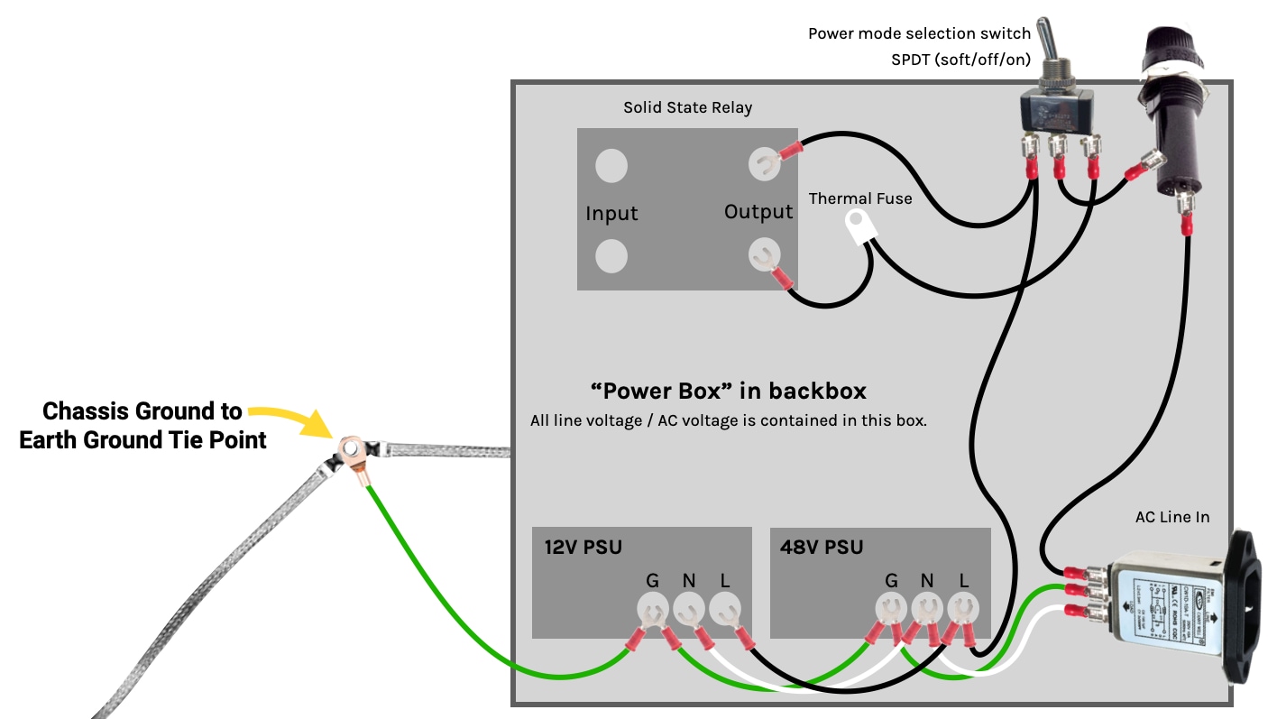
This should be inside or near your power box, and it should be a specific, intentional, and obvious connection. In other words, while there is almost definitely already an electrical path through AC wiring components and the ground braid, you want to make an intentional, solid connection point that won't vanish if some lid isn't screwed down tight.
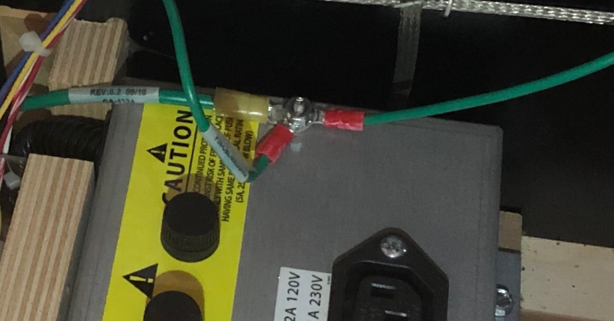
So make this a screw with ringed connectors under a locknut. If you have a metal cover for your power box lid, you can run a screw right through it. In fact if you take a closer look at the Attack from Mars Remake photo from above, notice that's exactly what they did: (The earth ground wire is attached to that same screw from the inside of the box.)
Do you tie DC ground to earth ground? It depends!
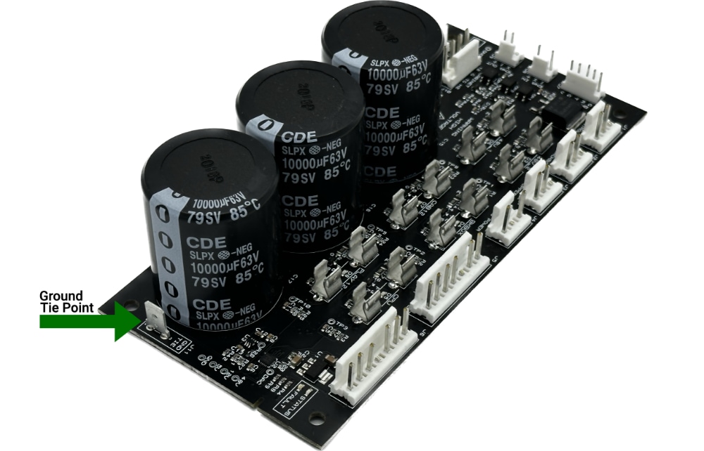
Now that you have your earth and chassis grounds connected, the next question is whether you should tie your DC grounds to earth ground. Recall from the previous guide that the smart power filter board has a tab for this:
However, this is not automatically something you want to do, as it depends on the specifics of your machine, power supplies, and specific scenario. So let's discuss this in more detail.
There are three options:
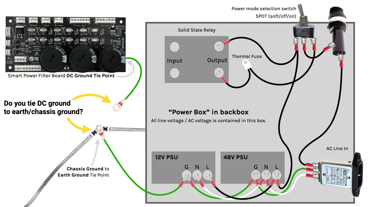
- Option 1. YES, tie them together. Add the wire from the filter board to the screw holding the earth and chassis grounds.
- Option 2. YES, tie them together, but through a capacitor, rather than a full wire connection.
- Option 3. NO, do not tie them together. Nothing is connected to the filter board ground tab.
Unfortunately there is no simple answer for which option you should choose. Well, actually, there is one simple answer. If you're getting your machine certified (UL, FCC, CE, etc.) or otherwise reviewed, then do whatever the inspector or Professional Engineer tells you to do! 😀
Some jurisdictions have specific guidance here, which, obviously if you have regulations which apply to this scenario where you live, then you should follow those.
Interestingly, in the United States, the NEC regulations dictate that tying DC ground to earth ground is required when DC voltage is higher than 60V. So this is why you'll see this tie in classic 90s machines which used voltage levels over that. But they don't say anything about voltages under that, and since our machines are 48V, there's not an automatic easy answer there.
This issue is complicated because there are scenarios where you'd want to tie them together, and other scenarios where you wouldn't. For example, in some cases, tying your DC ground to earth ground just puts 50/60Hz noise from the AC line into the DC grounds of your machine. D'oh! In other cases, it might actually solve noise problems.
One thing we can say for certain: If you chose to tie your DC ground to earth ground, you must do a test for voltage potential first. To do this, turn your machine on, but do NOT have anything connected to the ground tab on your filter board. (So you have the chassis and earth grounds tied together, but DC grounds are not connected in.) Now take your multimeter, set it to voltage measuring mode, and put one probe on your earth ground tie point and the other on the filter board ground tab. This will check to see if your DC ground and earth grounds are somehow connected or have potential between them. You want to find a low value here, most likely something in the millivolt range. (It doesn't matter which way the probes are connected—if the potential is the other way then you will just see a negative value.)
Again, your ideal is not much voltage at all. (Even with perfect separation, a few millivolts will come from the EMI from the AC line.) But anything over 2-3 volts is concerning. If you do see some voltage here, the next test is to see if this is just voltage potential, or actual moving current. For this test, switch your meter to current measuring mode (and maybe use the high current ports if you have them). Touch the probes to the same two locations and check the current. Hopefully it's zero. If you do have current here, then you absolutely DO NOT want to tie DC ground to earth ground, as earth ground is not allowed to carry any current. So in this case, you need to figure out where that current leak is coming from and address that first.
If you have little-to-no voltage potential across your DC ground tie and earth ground tie, that's great! But it doesn't automatically mean you can tie your DC ground to your earth ground. Why? Again, this gets into the specifics of your machine. As an example (and this is just one illustrative example, there are lots of other things a Professional Engineer would look for here), one concern is what happens if a power supply fails and puts voltage onto the earth ground? (This is actually possible, depending on your PSU and how it failed.) Obviously that should ideally blow your line fuse, but if there's a larger problem, this would now put AC voltage into your DC ground and you would have a very bad day.
So, again, whether you tie these together, (and whether you even want to tie these together) really depends on a lot of different factors. Luckily this connection is easy to add/remove, since it's just connecting or disconnecting a single wire to a single point. So if you have noise issues one way or the other, you can experiment and see what works best for your machine. (Again just do that voltage potential test first.)
N or > jump the next page, P or < for previous, search with S or ?